

Autumn is almost here and with that, hunting season. Hunting is so popular in my state that it is a non-official holiday where school is “canceled” and congress gets the day off. I’m not sure if that happens elsewhere but it is fair to say that hunting is a big part of our culture. Within the different components of a rifle or gun is the choice of a scope. There are different kinds of scopes, each with very specific optical requirements, designs, and performance. This article will try to explain the main difference between three of the most common scope designs: reflective, holographic, and telescopic sights. We will briefly define a sight as a device that allows the user to align an instrument (e.g. weapon, telescope) with a target. They may be mechanical or optical, passive or active.
Reflective sights
Reflective sights have been around since the 1900s, invented by Howard Grubb (1844-1931). Reflective sights are non-magnifying scopes with relatively simple configurations. This allows for reflective sights to be compact and low cost (you can buy one on-line for less than $50).
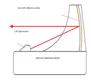
Reflective scopes consist of just a few optical elements: a light source, usually an LED, a reticle, a collimating lens, and a semi-reflective mirror. It is possible to replace the collimating lens and mirror with a single semi-reflective spherical mirror. This basic configuration (with a spherical lens) is shown in Figure 1.
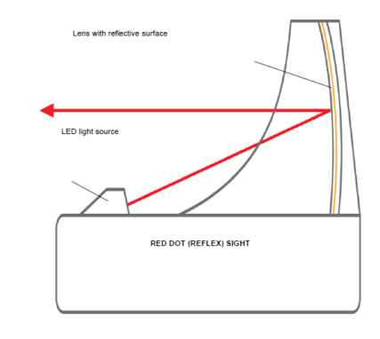

Figure 1. Reflex Sight. Image from EOTech
The basic optical operation is that the LED/reticle is placed at the focal point of the spherical mirror. The spherical lens in essence works as a collimating lens for the LED/reticle. The user can see through the spherical mirror and will see a virtual image of the reticle at infinity, superimposed on the target. A disadvantage of reflective sights over traditional iron-sight is the presence of a parallax effect: the crosshair moves along the target as the users move their eye position. This means that the crosshair may not be reflecting exactly where the rifle is aiming. Another disadvantage of reflective sights is that half of the LED optical intensity is lost on the semi-reflective mirror, thus making the reticle dim, especially in bright conditions. This can be solved by increasing the intensity of the LED itself and use of antireflection mirror coatings. These solutions however ncrease the price of the mirror and consume more power.
Holographic Sights
Holographic sights were first commercialized in 1996. They may look very similar to a reflective sight but they have very important differences. As we can see in Figure 2, holographic sight also has a light source that is being collimated by a spherical mirror. The reticle however, instead of being located at the focal point of the spherical mirror, is now placed at the exit window. Also the reticle is a holographic element, and as such, it needs to be illuminated by a coherent light source, usually a laser diode (instead of an LED as in the case of the reflective sight). The location and use of laser diodes as light sources have two main consequences: The first is that laser diodes consume more power than LED, so the battery use is higher in holographic sight than reflective sights. Another is that the parallax effect in holographic sights is reduced. A big advantage of holographic sights is that the reticle image is clearer than with reflective sights.
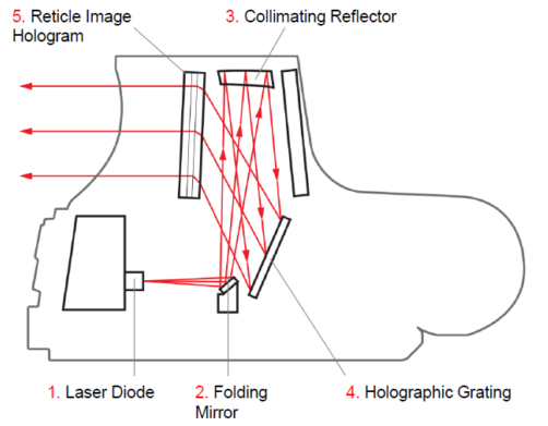

Figure 2. Holographic Sight. Image from EOTech
In general, holographic sights tend to be more robust, and provide a better reticle image than reflective sight. This comes with a bigger size and higher cost. They tend to be a better choice, unless price is your main restriction.
In Part 2, we’ll talk about telescopic sight. They are more complex in their design and require a larger explanation..
Also if you have any ideas of topics that you would like to read about send us a comment.
Telescopic Sights
Telescope sights are probably what most people have in mind when they think of a rifle scope. They were patented by John R. Chapman in 1844, although attempts to place a telescope on a rifle can be traced back to 1776 (without much success). Chapman’s scope used achromatic lenses to improve the image for the user. A fundamental improvement of Chapman’s design over previous attempts was an increase in eye relief: the distance between the scope and the user’s eye and scope. This was fundamental to avoid being hit in the eye by the recoil of the gun.
Elements of a rifle Scope
Figure 1 shows a typical telescopic sight. There are some basic optical elements. From the left, we have the objective lens. It is the main element that captures light; the larger its diameter, the more light it can capture.
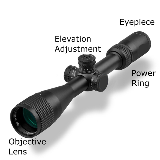

The objective lens will focus the light very close to the location of the elevation adjustment knobs. At this first focal plane, the reticle is placed. As in the sights previously described, the reticles can be a simple dot that the user superimposes on the target or more complicated geometry that will help the user compensate for effects of crosswind and bullet drop with distance. Reticles can be illuminated with an LED, and in many cases, the LED intensity can be adjusted depending on light conditions.
The position of the reticle in the main tube is controlled in the vertical and horizontal position by two adjustment knobs. The vertical adjustment is sometimes referred to as ballistic drop or bullet drop compensation while the vertical adjustment is usually referred to as windage control. By controlling these knobs, the user can better aim when strong crosswind is present and/or the target is placed at longer distances.
Behind the reticles, we have a set of erector zoom lenses. These lenses have two functions. One function is to correct the position of the image created with the objective lens. The objective lens inverts the image at its focal point and the image needs to be corrected before the eyepiece. The second function of the erector zoom lenses is to control the magnification power of the system. By rotating the power ring, the distance of the elements of the zoom lenses changes and it can magnify the image. In the current example, we have assumed that the reticle is placed in front of the erector zoom lenses. It is not unusual to see a design with the reticle is behind it.
Finally we have the eye piece. As with many other eye pieces, it main function is to create a virtual image that the user can see while relaxing his/her eye. Some eyepieces may include parallax correction elements (although it is more common to correct the parallax problem in the objective or erector lenses).
Finally, it is important to mention that many of the optical elements on a telescopic rifle tend to be coated. Usually, they may have different layers of coating, each of them with specific functions. You can add a protective coating to prevent scratching, and anti reflection coating to improve the transmission of light and to reduce glare.