Projection systems are one of the most common consumer optical devices (probably second to photographic systems). They allow us to view images on a screen (usually) by magnifying and projecting them at distances from a few centimeters to several meters away (like in a movie theater), while maintaining a high quality image. Projection systems are also used in industrial and scientific applications.
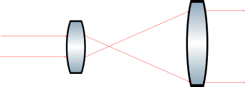
Typical designs allow for the image to be focused at different distances (zoom projector lenses); this requires multiple optical elements to work together and depending on the use, may need to provide continuous zoom or have discrete fixed zoom locations. Since the main purpose of a projection system is to create a high quality image, it is important to reduce all possible aberrations. In Figure 1, for example, we can see the combination of several double achromats used to reduce spherical and chromatic aberrations, as well as the use of negative and positive elements to correct for distortion and coma.

Figure 1. Example of a Projector and Condenser system. Image from Zemax
In addition to reducing aberration, there are different parameters to take into account when designing a projection lens. These parameters define the kind of illumination to be used, the working distance, and the location of the object and image with respect to the optical axis.
You can read more about the optomechanical methods to move lens groups for a zoom lens in this link.
Throw Ratio
Throw ratio is the relationship between the size of the image created on the screen and the distance at which the projector is placed. If a projector lens has a “small throw”, it means that it can be placed close to the screen and still produce a large image.
A small throw projector can be desirable because it can be placed in smaller rooms but it requires a more complex optical system design to reduce aberrations like distortion and chromatic aberration and this can lead to higher prevision element which means higher costs systems.
Offset
Offset refers to a shift of the object from the center of the optical axis. This creates an image that will also be displaced from the optical axis. Offset is sometimes required to avoid obstruction of the image by objects along the optical axis; for example, if the projector is sitting on a table, the table may block part of the image, or if the projector is close to the ceiling, we want to avoid blocking the image by it. It is possible to design systems with variable offsets but that requires a more complex optical design. It is more common, and cost effective, to design systems with a fixed offset (usually between 100% – 130%).

Figure 2. Optical projector with a 150% vs 0% offset. The object and image are displaced from the optical axis. Image from Texas Instrument
Illumination: Telecentric vs. Non-Telecentric
The illumination configuration can be telecentric or non-telecentric. In a telecentric system, the angle of incidence of light illuminating the object is constant which in return creates a more uniform brightness on the image. They can be designed with a variable offset (from 0% – 130%). The illumination system can be independent from the projection lens, so it’s possible to exchange one without modifying the other. As a drawback, they tend to be more expensive and include more elements than a non-telecentric system.
In a non-telecentric system, the illumination is not constant and it’s usually at an offset angle, so the image brightness is also affected by this. They tend to have a lower cost than a telecentric system, but they have more design limitations. As an example, all non-telecentric systems have to have a fixed offset.

Figure 3. Illumination systems. Telecentric vs non-telecentric. Image from Texas Instruments