3D Mapping Technology
Astigmatic Depth Mapping — US Application No. 14/256,085
OFH has extensive expertise in 3D mapping, distance measurement, and has worked on LIDAR, stereo imaging, time of flight, computational photography, light coding, structured illumination, and many more methods. Our clients have sold millions of units and are global leaders in robotic vision.
Below we describe a new approach developed by OFH. This method uses a pattern projector and an astigmatic lens placed in front of an image sensor to generate a depth map.
- LIDAR
- Stereo Imaging
- Time of Flight
- Light Coding
- Structured Illumination
Technology Overview
A four-step process that converts projected spot patterns into accurate depth measurements using astigmatic image analysis.
Key Benefits
This approach offers significant advantages over traditional time-of-flight and other depth measurement methods.
No Multi-Path Interference
Unlike time-of-flight systems, this method is not sensitive to multi-path interference caused by unwanted reflections from angled surfaces.
Ambient Light Resilient
Less sensitive to changes in object reflection/scattering or ambient light variations, because the method relies on changes in spot shape (not spot intensity) to determine distance.
Ultra-Compact Form Factor
System can be very small; in fact, the performance is better when the projection axis and collection path are next to each other.
Passive Mode Available
For certain applications, the system may be used without a projected pattern, relying on existing scene features for depth extraction.
Concept
By adding astigmatism to the image collecting objective lens, the shape of the point spread function (PSF) becomes dependent on the distance to the object.
Astigmatic Point Spread Function
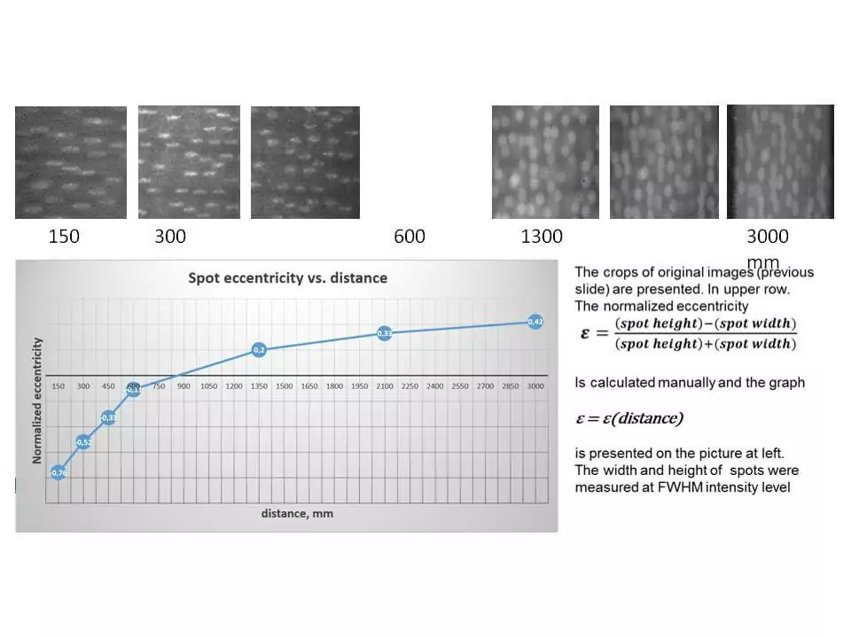
The eccentricity ε of the elliptical PSF varies with the distance to the object. By measuring the ratio of the long axis to the short axis of each projected spot as captured by the sensor, we can directly compute the distance to the surface at that point.
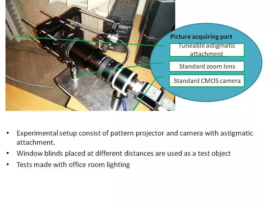
The experimental setup consists of a pattern projector and camera with astigmatic attachment. Window blinds placed at different distances are used as a test object. Tests were made with standard office room lighting.
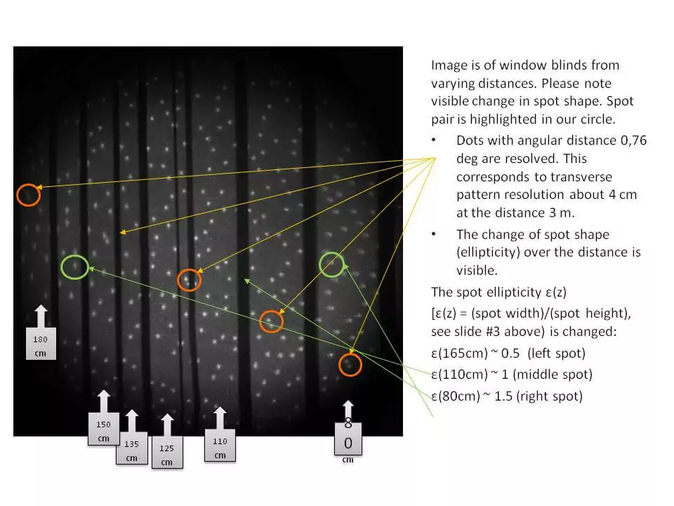
The spot ellipticity ε(z) = (spot width)/(spot height) changes with distance:
ε(165cm) ≈ 0.5 (left spot)
ε(110cm) ≈ 1.0 (middle spot)
ε(80cm) ≈ 1.5 (right spot)
Accuracy and Range
The astigmatic attachment can be optimized based on the required distance measurement range, distance measurement (longitudinal) accuracy, working wavelength, and projected pattern geometry.
The distance map transversal resolution depends on the number of spots projected. Resolution, accuracy, and repeatability are influenced by sensor quality and imaging lens quality.
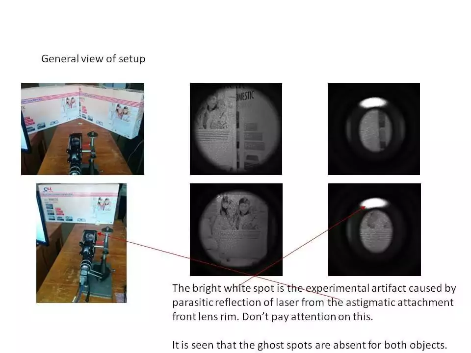
Multipath Error Advantage
Multi-path error is a characteristic feature of TOF-based rangefinders and is caused by unwanted reflections from object surfaces placed at an angle.
Our proposed solution belongs to the “Depth from Defocus” class of range finding methods which are based on picture analysis, not from analysis of light phase shifts used in TOF systems.
The multi-path error is most perceptible when the angle between surfaces is 90° because the returning light goes exactly in the opposite direction. We have tested this worst case by means of two surfaces (glossy paper coated carton) placed at a 90° angle.
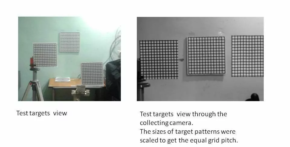
Alternative Method — Passive Layout
The passive layout means that the system does not use structured illumination. The distances from the camera to the test targets are: left — 1.2 m, middle — 2.70 m, right — 0.50 m.
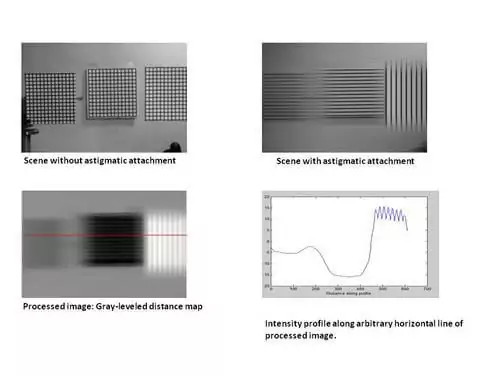
Advantages
- Low sensitivity to illumination variations over the entire scene
- Low sensitivity to different colors of the scene
- Easy adaptability to off-the-shelf lens and/or specific distance range requirements
Limitations
- Cannot resolve the “White Wall” problem — object needs surface with optically resolvable features
- These limitations can be reduced by updating picture processing algorithms or eliminated by adding a structured pattern projector (transforming passive into active)