Custom VIS-NIR Dual-Band Imaging Lens for Fluorescence-Guided Surgery
Optics for Hire
491 Massachusetts Ave., Suite 206B · Arlington, MA 02474
www.opticsforhire.com · (781) 583-7810
1. Executive Summary
Optics for Hire (OFH) designed a custom 35 mm f/1.65 imaging lens for a medical imaging company developing a fluorescence-guided surgical camera system. The system must simultaneously image in the visible (VIS) spectrum for standard white-light surgical visualization and in the near-infrared (NIR) at 800–950 nm for real-time fluorescence detection of tumor-marking agents — without refocusing between the two modalities.
The existing catalog lens (Edmund Optics #85362) was found to have a 205 µm chromatic focal shift between VIS and NIR — too large for simultaneous sharp imaging in both bands. OFH designed a replacement 7-element, 5-group lens optimized in ZEMAX to cut this shift to 95 µm across the full VIS+NIR range, while maintaining the same 35 mm focal length, f/1.65 aperture, 22 mm diameter, and compact 37 mm barrel length of the original lens.
VIS+NIR chromatic focal shift reduced from 205 µm (Edmund catalog lens) to 95 µm (OFH custom design) — a 54% improvement. VIS MTF maintained at 0.5+ at 40 cy/mm on-axis. NIR MTF dramatically improved to match VIS. 0.25 mm objects resolved at all working distances in VIS and NIR. Distortion < 0.5%. Compatible with both 2/3" and 1/1.2" sensors. A complete optomechanical design (12-part assembly, 18 fabrication drawings) was developed. Physical prototype testing confirmed all specifications met or exceeded across the full 250–550 mm working distance range in both VIS and NIR without refocusing.
2. Background & Clinical Context
2.1 Fluorescence-Guided Surgery
The client's system is designed for use with a Zeiss Pentero surgical microscope. The camera attachment replaces or augments the standard color camera, adding NIR fluorescence imaging capability to allow surgeons to visualize tumor-specific fluorescent agents during resection. The fluorophore is excited at 785 nm and emits in the 800–950 nm range, with the dominant contribution between 820–900 nm.
The key requirement driving the lens design was the need for simultaneous VIS and NIR imaging without mechanical refocusing. In clinical use, the surgical field is always illuminated by white light (which cannot be controlled), so the camera captures VIS light continuously. The NIR fluorescence is captured by strobing the 785 nm excitation laser. Any focus shift between the VIS and NIR channels directly degrades image quality of the surgeon's primary diagnostic tool.
2.2 Deployment Platform
The imaging head incorporates a dichroic beamsplitter that routes VIS and NIR light to separate sensors. Two custom filters are also required in the optical path: an emission cleanup notch filter (blocking the 785 nm excitation laser from reaching the NIR sensor) and a long-wave-pass visible-cut filter (blocking visible wavelengths above ~650 nm from the NIR channel to eliminate magenta color hue on the visible sensor). The lens must maintain performance with these filter substrates in the back focal distance region between the lens rear element and the image sensor.
The imaging sensor is a Sony 1/1.2" format (11.3 × 7.1 mm, 5.86 µm pixels, 1920 × 1200). The existing Edmund lens was designed for a 2/3" sensor, and the custom OFH lens was designed to cover at minimum the 2/3" image circle with a goal of covering the full 1/1.2" sensor (8.5° diagonal half-angle).
The entire optical layout was modeled in Zemax to ensure correct performance.
3. Baseline Analysis: Edmund Optics Lens
3.1 Edmund Optics #85362 — Specifications
OFH performed a full ZEMAX analysis of the existing Edmund Optics 35 mm f/1.65 lens (catalog #85362) using the manufacturer's black-box model. This analysis established the performance baseline and identified the limitations driving the custom design.
| Parameter | Edmund #85362 |
|---|---|
| Focal length | 35 mm (fixed) |
| F-number | f/1.65 |
| Sensor format (design) | 2/3" |
| Working distance range | 100 mm to infinity (analyzed: 250–550 mm) |
| Optimal WD range | 350–500 mm (optimized by manufacturer) |
| VIS MTF (on-axis, 40 lp/mm) | 0.3+ at 400 mm WD, drops to 0.2+ at 250 mm |
| VIS chromatic focal shift | 36 µm (486–656 nm) — acceptable |
| VIS+NIR chromatic focal shift | 205 µm (486–950 nm) — too large for simultaneous imaging |
| Distortion (VIS) | < 0.16% at field edge |
| Distortion (NIR) | < 0.20% at field edge |
3.2 The Chromatic Focal Shift Problem
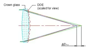
The fundamental limitation of the Edmund lens for this application is its large VIS-to-NIR chromatic focal shift. A standard visible-corrected apochromat manages chromatic aberration across the visible spectrum (approximately 400–700 nm) but is not corrected into the NIR. The Edmund lens shows only 36 µm of focal shift across the visible band — well within the depth of focus — but 205 µm when the full VIS+NIR range (486–950 nm) is considered. At f/1.65, the depth of focus is on the order of ±30–50 µm, meaning the Edmund lens cannot simultaneously focus both VIS and NIR on the same sensor plane without one channel being significantly defocused.
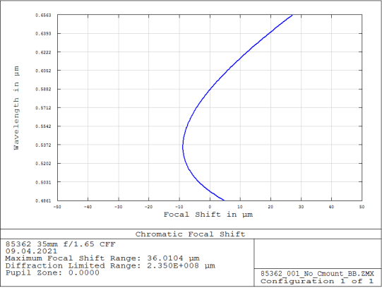
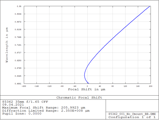
Figure 1: Edmund Optics #85362 chromatic focal shift. Left: VIS only (486–656 nm) — 36 µm, acceptable. Right: VIS+NIR (486–950 nm) — 205 µm, far exceeding the depth of focus. This prevents simultaneous sharp VIS and NIR imaging without refocusing.
4. Custom Lens Design
4.1 Design Philosophy
The design goal was to create a drop-in replacement lens that matches the Edmund lens form factor as closely as possible — same focal length (35 mm), same aperture (f/1.65), same approximate diameter (~22 mm) and length — while solving the chromatic correction problem. Rather than specifying a completely new form factor that would require new mechanical housing design, OFH worked within the constraints of the existing imaging head geometry.
The custom lens was designed and optimized in ZEMAX over a 3-week period, incorporating simultaneous multi-configuration optimization across three working distances (250, 400, and 550 mm) and both wavelength bands (VIS: 486–656 nm and NIR: 820–950 nm). The design was carried through full tolerance analysis before being released for optomechanical packaging.
4.2 Lens Architecture — 7 Elements, 5 Groups
The final design consists of 7 lens elements organized in 5 groups. The increased element count compared to a standard industrial lens (typically 5–6 elements) is required to simultaneously correct the additional degree of chromatic aberration across the extended VIS+NIR wavelength range, while maintaining a fast f/1.65 aperture and compact overall length. The lens uses standard catalog glass types to keep manufacturing cost manageable.
| Parameter | Custom OFH Lens |
|---|---|
| Focal length | 35 mm |
| F-number | f/1.65 |
| Lens elements / groups | 7 elements / 5 groups |
| Outer diameter | 22 mm |
| Barrel length | 37 mm |
| Back focal length | 15.6–18.3 mm (varies with WD: 250–550 mm) |
| Working distance range | 250–550 mm |
| Wavelength coverage | VIS 486–656 nm + NIR 820–950 nm |
| Sensor format | 2/3" (full coverage), 1/1.2" (extended coverage) |
| Max angular FOV (1/1.2") | ~9–9.5° half-angle diagonal |
| Glass materials | Standard catalog glasses |
5. Optical Performance
5.1 MTF — Visible and NIR
The modulation transfer function (MTF) was computed for three working distances (250, 400, and 550 mm) and for three field positions (on-axis: 0 mm, 3 mm, and 5.5 mm image height) in both the VIS and NIR bands. The NIR MTF was computed without refocusing — i.e., at the same back focal distance as the VIS focus — demonstrating the practical simultaneous-imaging performance.
The VIS MTF at the optimized working distances (300–450 mm) is maintained above 0.5 at 40 cy/mm on-axis, with graceful roll-off toward the field edge. The NIR MTF, which was degraded on the Edmund lens due to the large chromatic focal shift, is now closely matched to the VIS performance — the primary design goal.
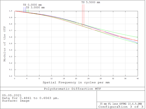
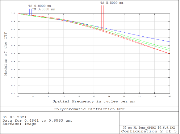
Figure 4: Polychromatic diffraction MTF at 550 mm working distance. Left: VIS band (486–656 nm) — on-axis MTF > 0.5 at 40 cy/mm, maintained across field. Right: NIR band (820–950 nm, without refocus) — MTF closely matches VIS, demonstrating the success of the broadband chromatic correction. Three field positions shown: on-axis (0 mm), 3 mm, and 5.5 mm image height.
5.2 Chromatic Focal Shift
The chromatic focal shift is the central performance metric for this application. The custom OFH lens achieves a VIS+NIR focal shift of 95 µm — compared to 205 µm for the Edmund lens — a 54% reduction. The VIS-only focal shift (37 µm) is essentially unchanged from the Edmund baseline (36 µm), confirming that the extended NIR correction was achieved without compromising the VIS-band correction.
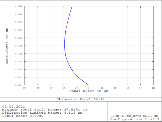
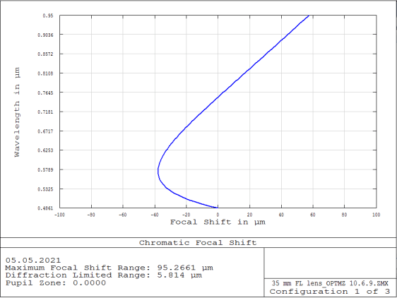
Figure 5: Custom lens chromatic focal shift. Left: VIS only (486–656 nm) — 37 µm, matching the Edmund baseline. Right: Full VIS+NIR range (486–950 nm) — 95 µm, reduced from 205 µm on the Edmund lens (54% improvement). The remaining 95 µm shift falls within the acceptable range for simultaneous imaging at f/1.65 after accounting for the depth of focus at the working distances of interest.
VIS+NIR chromatic focal shift: Edmund 205 µm → OFH Custom 95 µm. This 54% reduction enables simultaneous sharp VIS and NIR imaging without refocusing — the fundamental clinical requirement for the fluorescence-guided surgical system.
5.3 Field Curvature and Distortion
Field curvature and distortion are critical for surgical imaging — field curvature causes the image to be sharp only in a limited zone, while distortion causes geometric inaccuracy in surgical measurements. The custom lens achieves excellent performance on both metrics across the full VIS+NIR wavelength range simultaneously.
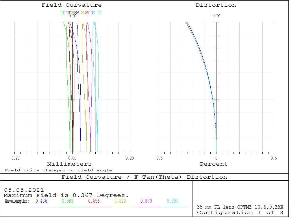
Figure 6: Field curvature and F-tan(θ) distortion diagram for the custom lens, computed over the full VIS+NIR wavelength range (486–950 nm) at 8.4° maximum field angle. Field curvature < 0.1 mm across all wavelengths. Distortion < 0.5% at field edge. Multiple wavelength traces (486 nm blue through 950 nm cyan) overlay closely, confirming good chromatic field correction.
5.4 USAF Resolution Simulations
Extended diffraction image analysis (USAF target simulation) was performed in ZEMAX for three working distances and both wavelength bands, using 0.25 mm line width objects — the target resolution requirement for the system (resolving 500 µm features, the minimum tumor resection target). The simulations confirm clean resolution of 0.25 mm objects in both VIS and NIR at all working distances from 250 mm to 550 mm.
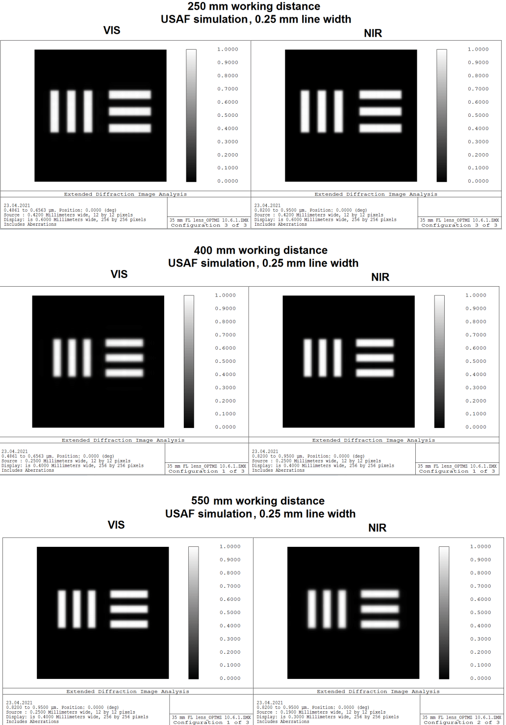
Figure 7: ZEMAX USAF resolution simulations at 250 mm, 400 mm, and 550 mm working distances (top to bottom), for VIS (left column) and NIR (right column). All simulations use 0.25 mm line width targets. The target features are cleanly resolved in both channels at all three working distances, meeting the clinical requirement for 500 µm feature detection.
6. Performance Comparison: Custom vs. Edmund
| Metric | Edmund #85362 | OFH Custom Lens | Improvement |
|---|---|---|---|
| VIS chromatic focal shift | 36 µm | 37 µm | Maintained |
| VIS+NIR chromatic focal shift | 205 µm | 95 µm | 54% reduction ✓ |
| VIS MTF on-axis (40 cy/mm, 550 mm WD) | ~0.3+ | ~0.5+ | Improved ✓ |
| NIR MTF (without refocus) | Severely degraded | ~0.4+ | Major improvement ✓ |
| Distortion (VIS) | < 0.16% | < 0.5% | Acceptable |
| Distortion (NIR) | < 0.20% | < 0.5% | Acceptable |
| Field curvature | < 0.1 mm | < 0.1 mm | Maintained |
| Outer diameter | ~28 mm | 22 mm | Reduced ✓ |
| Barrel length | ~50 mm | 37 mm | More compact ✓ |
| Back focal length | 16–18.9 mm | 15.6–18.3 mm | Compatible ✓ |
| Sensor coverage | 2/3" | 2/3" + 1/1.2" | Extended ✓ |
| Simultaneous VIS+NIR focus | No | Yes | Key capability ✓ |
7. Filter System Integration
The imaging head requires two custom filters in the optical path, the specifications for which were developed in parallel with the lens design. OFH reviewed the filter design requirements document and incorporated the filter substrates into the ZEMAX model to ensure the lens back focal length accommodates the filter stack between the rear element and the image sensor.
- Emission Cleanup Notch Filter: Blocks the 785 nm excitation laser wavelength from reaching the NIR imaging channel. Custom filter design required due to the narrow blocking band and the need to maintain transmission across 800–950 nm.
- Long-Wave-Pass Visible-Cut Filter: Blocks visible wavelengths above ~650 nm from the visible channel, preventing a magenta color hue caused by NIR-sensitivity of the CMOS sensor. 4% visible-cut design.
The filter substrates (glass type and thickness) were incorporated into the ZEMAX back focal distance model. Final filter specifications were being finalized in parallel with the lens design, and the lens back focal length range (15.6–18.3 mm) provides sufficient accommodation for the combined filter stack while maintaining compatibility with the camera sensor interface.
8. Optomechanical Design
Following completion and tolerance analysis of the optical design, OFH performed a full optomechanical design of the lens assembly. This phase translated the optical prescription — seven elements in five groups — into a complete, fabrication-ready mechanical package with GD&T-controlled dimensions, material specifications, surface finish requirements, and individual part drawings for all components.
8.1 Assembly Architecture
The lens barrel is a 12-part assembly housed in a single-piece aluminum barrel. The total assembly length is 40 mm with an optical path depth of 22.4 mm. The image-side mount is M19×0.5 thread with a Ø22 mm f8 fit for camera body interface. The object-side entrance aperture is Ø28 mm (M25×0.5 thread).
The five optical groups are retained by a front retainer and rear retainer, with three precision aluminum spacers controlling the axial air gaps between groups. An aperture stop is positioned between the front and rear optical groups. The housing bore diameters have defined tolerances and circularity and coaxiality callouts to ensure optical alignment along the optical axis.
8.2 Optical Element Specifications
Individual fabrication drawings were produced for all five optical elements (or cemented sub-assemblies). Each drawing specifies: surface radii, clear aperture diameters, center thickness, glass type with refractive index and Abbe number tolerances, surface figure (irregularity), surface roughness, centering tolerance (tilt in arcmin and decentration in mm), and coating requirements. All coatings are specified as broadband anti-reflection (ARC R<0.5%) across 450–670 nm and 800–950 nm — the two operating wavelength bands.
The front group consists of a singlet and a cemented doublet. The rear group is a symmetric followed by a final singlet. Edge blackening is specified on all singlet and doublet elements to suppress stray light.
OFH provides end-to-end lens design services from optical prescription through fabrication-ready optomechanical drawings. The project demonstrates OFH's capability to take a 7-element, dual-waveband optical design from ZEMAX prescription to a complete 12-part mechanical assembly drawing package, ready for precision machining and optical fabrication.
9. Prototype Fabrication and Physical Testing
Following the completion of the optical design, optomechanical design and tolerance analysis, the complete drawing package — 18 drawings at Revision A — was provided to an OFH fabrication partner. Five prototypes were built and delivered to the client and OFH for physical testing. Optical bench measurements were performed by OFH engineers.
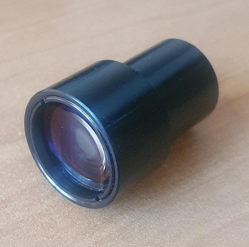
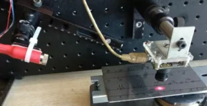
Lens prototype used for testing
9.1 Test Equipment and Method
Testing was performed on an optical bench using manual translation stages for focus adjustment and target positioning. Illumination sources were a high-power white LED source for VIS measurements and Osram SFH 485 LEDs (880 nm peak, 80 nm bandwidth) for NIR measurements. A USAF 1951 test chart was used for all resolution measurements.
Measurements were taken at working distances of 250, 300, 350, 400, 450, 500, and 550 mm. Resolution was assessed at three field positions for each working distance and each wavelength band: center of field, side of field (end of horizontal axis), and corner of field.
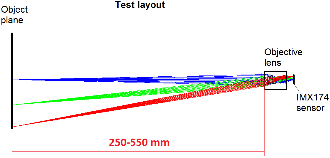
Figure 8: OFH optical test bench setup for prototype lens evaluation. Camera (IDS UI-3060CP, 1/1.2" sensor), USAF 1951 test target, VIS and NIR LED sources, and precision translation stages
9.2 Field of View and Distortion Measurements
Field of view was measured at 400 mm working distance using a 1 mm × 1 mm grid-of-lines target. The lenses produced a measured FOV of approximately 130 × 80 mm at this working distance, in close agreement with the ZEMAX model predictions. Distortion was assessed from the grid images using the F-tan(θ) metric. Measured distortion was less than 1% (approximately 0.6–0.7%) for both lenses, consistent with the ZEMAX simulation result.

Figure 9: Grid-of-lines image (1 mm × 1 mm cell size) at 400 mm working distance, Lens 8. Measured FOV ≈ 130 × 80 mm. Distortion is visually negligible; calculated F-tan(θ) distortion < 1%, consistent with ZEMAX model.
9.3 Resolution Measurements — VIS and NIR
Resolution was measured using the USAF 1951 test target at all seven working distances (250–550 mm) at center, side, and corner field positions, in both VIS and NIR without refocusing. The key specification is the ability to resolve Group 1 Element 1 of the USAF target, corresponding to 0.25 mm line width at the object plane — the minimum feature size required for the fluorescence-guided surgical application.
The tested lenses resolved Group 1 Element 1 (0.25 mm) at all field positions and all working distances from 250 mm to 550 mm, in both VIS and NIR without refocusing. This result directly confirms that the simultaneous VIS+NIR focus design is performing as simulated. Representative images at 250 mm working distance (the most demanding case for the optic) are shown below.
VIS — Center | Side | Corner (250 mm working distance, Lens 8)
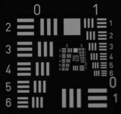
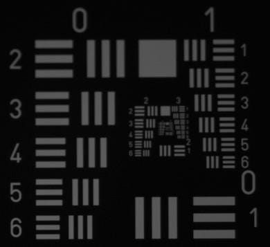
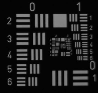
NIR (880 nm, no refocus) — Center | Side | Corner (250 mm working distance, Lens 8)
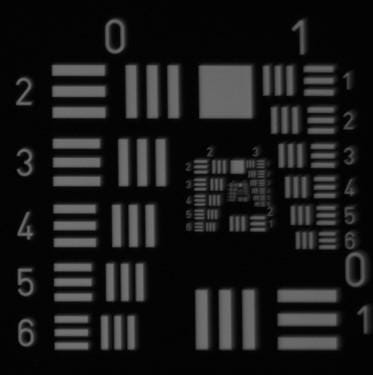
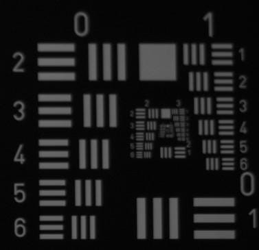
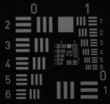
Figure 10: USAF 1951 test target images at 250 mm working distance, Lens 8. Top row: VIS illumination — center, side, and corner field positions. Bottom row: NIR illumination (880 nm, no refocus) — same field positions. Group 1 Element 1 (0.25 mm line width) is resolved in all six images, confirming simultaneous VIS+NIR focus performance across the full field of view.
9.4 Prototype Test Summary and Client Validation
Measured focal length and back focal length for both prototype lenses agreed closely with the ZEMAX model. All measured parameters fell within the tolerance band established by the tolerance analysis performed during design.
Both prototype lenses met or exceeded all optical specifications across the full working distance range of 250–550 mm in both VIS and NIR without refocusing. 0.25 mm features resolved at center, side, and corner field positions at all working distances. FOV and distortion confirmed consistent with ZEMAX model. Client confirmed: "these lenses have met or exceeded our expectations in every way."
The two fabricated prototype lenses were retained by OFH following the testing period to provide a reference set for parallel testing in the event of any field issues, and to support evaluation of any mechanical updates required for production — including threading changes and filter holder integration.
10. Technical Significance
This project addresses a commonly encountered challenge in medical imaging: extending a precision imaging lens from the visible spectrum into the NIR without compromising either channel's performance. The key technical contributions of the OFH design work were:
- Broadband apochromatic correction extending from 486 nm to 950 nm — a 460+ nm spectral range — while maintaining f/1.65 aperture and compact form factor.
- 54% reduction in VIS+NIR chromatic focal shift enabling simultaneous imaging in both channels without mechanical refocusing, directly enabling the real-time fluorescence visualization capability.
- Drop-in compatibility with the existing surgical microscope attachment housing — same focal length, similar diameter and length, compatible back focal distance — minimizing system redesign risk.
- Extended sensor coverage: the custom lens covers the 1/1.2" sensor format used in the Scorpion 2 system, whereas the Edmund lens was rated for the smaller 2/3" format.
- Multi-configuration ZEMAX optimization across three working distances and two spectral bands simultaneously, producing a balanced design rather than one optimized for a single operating point.
OFH brings deep experience in biomedical and surgical imaging lens design, including dual-band VIS/NIR systems, fluorescence imaging optics, and medical device optical systems requiring tolerance analysis and manufacturing-ready documentation.
11. About Optics for Hire
Optics for Hire (OFH) is an optical engineering consultancy based in Arlington, Massachusetts, serving clients from startups to Fortune 50 corporations since 2002. Our 12-person R&D team includes physicists, optics PhDs, and mechanical, electrical, and software engineers with deep expertise in imaging and illumination system design.
OFH capabilities directly relevant to medical and surgical imaging include:
| Imaging Optics | Medical Devices | Electronics & Software | System Integration |
|---|---|---|---|
| Surgical & fluorescence cameras, night vision, self-driving car optics, objective lenses | Ophthalmoscopes, endoscopes, otoscopes, thermal medical devices, DNA imaging | Autofocus electronics, CCD/CMOS drivers, laser spectrometer signal processing | VR/AR optics, laser distance measurement, optical metrology, fluorescence signal processing |
Relevant Project Expertise
- ZEMAX sequential optical design & optimization
- Dual-band VIS/NIR imaging lens design
- Fluorescence & surgical imaging systems
- Broadband chromatic aberration correction
- Tolerance analysis & optical drawings
- Medical device optical system integration
- Sensor, filter & dichroic system modeling