Structured-Light Stereovision System for Parcel and Package 3D Dimensioning
Optics for Hire
491 Massachusetts Ave., Suite 206b · Arlington, MA 02474
www.opticsforhire.com · (781) 583-7810
1. Executive Summary
Optics for Hire (OFH) was hired by a logistics and warehouse automation technology company. The goal was to design a custom structured-light stereovision system for real-time 3D package dimensioning. This product is used on conveyor lines of logistics hubs, fulfillment centers, and sorting facilities for the measurement of the parcels and packages. The client needed a solution to replace a discontinued commercial product with the same or higher characteristics and accuracy and a comparable system cost.
OFH developed the functioning bench-top prototype of the stereovision system, including the 3D mapping algorithm, satisfying the client's requirements. The Structured-Light Stereovision principle was chosen because of its high enough accuracy for the short and middle distances, reliability, and low cost of realization.
Distance to object measurement error
· 0.9 mm for the 700 mm – 1500 mm functioning range — meets the requirements ±3.5 mm.
· 10.5 mm for the 700 mm – 4000 mm functioning range — meets the requirements ±30 mm.
Maximum object size measurement error
· 3.8 mm at 1500 mm distance — stretch goal ±3 mm.
· 17.2 mm at 4000 mm distance — stretch goal ±7.5 mm.
Average object size measurement error (5 consecutive measurements)
· 1.42 mm at 1500 mm distance — meets the requirements ±3 mm.
· 7.12 mm at 4000 mm distance — meets the requirements ±7.5 mm.
The prototyping results meet the requirements. Further modification of the 3D mapping algorithm and hardware will reduce the number and amplitude of the size estimation errors during single measurements.
2. Background & Technical Challenge
2.1 Application Context
The existing component used by the client relied on the depth camera using the structured light. The existing component was discontinued. This created an urgent need for a custom alternative device that could be manufactured and serviced independently to reduce risks. The alternative needed to work for different-sized and material objects in different illumination conditions and contain available and easily replaceable off-the-shelf parts.
The key requirements provided for the custom alternative were:
- Working distance range: 700–1500 mm (700–4000 mm if possible)
- Distance to object measurement error: ±3.5 mm in the 700–1500 mm range, ±30 mm in the 700–4000 mm range
- Object size measurement error: ±3 mm in the 700–1500 mm range, ±7.5 mm in the 700–4000 mm range
- Field of view (FOV): 70° diagonal
- Eye-safe infrared illumination (IEC Class 1 laser safety)
- Manufacturable at a competitive per-unit cost
- Real-time object data processing and processing with the stored data
2.2 Why Structured-Light Stereo?
Passive stereo vision, when two cameras are without active illumination, struggles on textureless surfaces such as plain cardboard boxes. Projecting a pseudo-random dot pattern onto the scene creates artificial texture. The stereo correspondence algorithm can match reliably on any surface with such a projection. The commercial depth cameras use a similar way for the textureless surfaces issue to resolve. The custom decision provides wide variability and adjustability of the depth camera characteristics, such as FOV, working distance, and pattern projector power and wavelength band. An additional advantage is in the algorithm flexibility, which can be optimized for the replaced hardware or changed conditions or requirements.
Stereovision is based on the comparison of the images from the cameras placed at some distance from one another. Placement of the object spot image at the cameras differs and depends on the distance between the cameras ("base"), distance to the object, and focal length of the lenses. The shift of the spot image on the first camera relative to the second camera is disparity. Disparity changes through the image if the object has relief. Disparity change comparable with a pixel size provides not high accuracy of the distance estimation. Higher accuracy requires higher resolution of the image or a longer base of the stereovision system, which affects the system size and final cost.
Alternative option is using the subpixel accuracy algorithms. To correspond to the size, cost, and accuracy requirements, the design of the developed system is based on the usage of such an algorithm. The base of 150 mm provides a 1.3 µm disparity if the 1500 mm placed object shifts ±4 mm. The shift of the image at the camera can be much shorter than one pixel. Subpixel algorithm estimates pixel irradiance changes to estimate image shifts (disparity) with accuracy higher than the size of the camera pixel.
3. System Architecture
3.1 System Overview
The stereovision system comprises three optical channels mounted on a common rigid baseline:
- Left camera: 5 MP monochrome sensor, IR-pass, wide-angle lens
- Right stereo camera: identical to the camera, placed at 150 mm baseline separation
- Pattern projector: pseudo-random IR dot pattern, eye-safe Class 1, ~57,000 dots
- Visible range camera (optional): provides an RGB image of the package for different warehouse operations such as tracking and reports
All channels are mounted on a machined aluminum rail. The fastening elements are customized to ensure adjustment for parallelism and convergence of the left and right cameras.
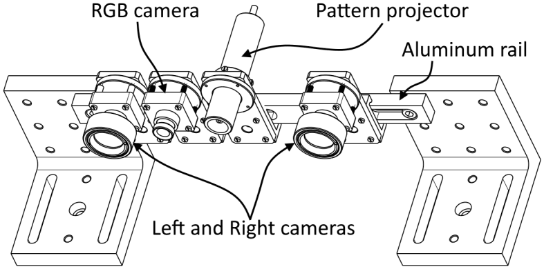
Figure 1: Layout of Stereovision System
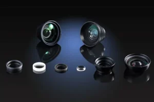
3.2 Optical Components Selected
| Parameter | Value / Notes |
|---|---|
| Stereo camera sensor | Basler daA2500-14um (5 MP (2592 × 1944), 2.2 µm pixel, 1/2.5", USB 3.0) |
| Stereo lens | CCOM 123043MPF (4.3 mm focal length, 85.4° diagonal FOV (67.1° × 52.9°), 14 MP resolution, F/2.8, TV-distortion < -1.2%) |
| Pattern projector | Osela RPP017 pseudo-random dot projector (57,446 dots, 45° × 45° FOV, 830 nm wavelength, eye safe) |
3.3 Pattern Projector Selection
The projected pattern must satisfy three key requirements simultaneously:
- Density: enough dots per unit area to support ±3 mm accuracy for the object edge detection. Required dot spacing is ≤ 6 mm at a 1500 mm working distance. It is implying a ≥ 277 × 192 dot resolution of the pattern across the 1663 × 1152 mm scene.
- Signal-to-noise ratio: sufficient IR signal above background noise on the sensor for reliable pattern localization on the image.
- Uniqueness: the pattern must be locally unique within the chosen window size to prevent false detection of similar pattern areas placed in different pattern areas.
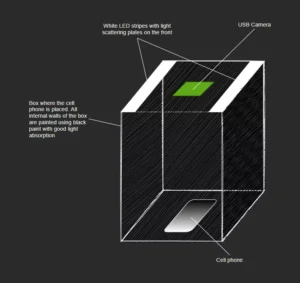
After the initial search for the suitable projector, OFH decided to test two of the market-available ones mostly corresponding to the requirements.
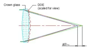
- Projector that is based on the slide projection principle and uses a LED as a radiation source.
- Projector that is based on a diffractive optical element (DOE) and uses a laser diode as a radiation source.
After the lab tests, the Osela RPP017 random dot projector containing DOE and generating 57,446 dots within a 45° × 45° cone was identified as the best available commercial pattern projector suitable for the device prototyping and further development of the 3D mapping algorithm.
4. ZEMAX Optical System Modeling
OFH created a full optical model (Zemax OpticStudio) of the complete stereovision system to simulate its functioning. The model contained two stereovision cameras, a pattern projector, and an object. Form, size, and optical properties of the object can be chosen on the form, size, and optical properties of the simulated object. The model made it possible to:
- Verify sensor irradiance levels across F/#, working distance combinations, and object optical properties
- Confirm requirements to the type of the chosen pattern and its dot density at the object space
- Generate synthetic left/right stereo image pairs for algorithm development and validation
- Establish the theoretical depth resolution limit as a function of base, focal length, and sensor pixel size
The ZEMAX model used different types of reflection/scattering from the object surface. The optical model confirmed that the chosen F/2.8 lens aperture provided enough high signal-to-noise ratio for the camera sensor across the full 700–4000 mm working distance range within the Class 1 projector power envelope for the most optical properties simulated for different types of boxes and packaging used in postal forwarding.
5. 3D Mapping Algorithm
5.1 Stereo Triangulation Principle
The depth measurement principle is classical stereo triangulation. For a point on an object at depth z:
z = (b × f) / d
where: b = baseline (150 mm) · f = focal length (4.3 mm) · d = disparity (pixels × pixel pitch)
The critical insight driving algorithm design is that the disparity difference for the object placed at 1500 mm and 1504 mm distances is only 1.1 µm. The shift of the spot image at the cameras can be much smaller than the pixel pitch. Achieving the required ±4 mm depth detection accuracy therefore demands subpixel disparity estimation, not pixel-accuracy correspondence alone.
5.2 Sum of Absolute Differences (SAD) Correlation
The core correspondence algorithm uses Sum of Absolute Differences (SAD) computed for each candidate disparity value at each image pixel:
- For each pixel (i, j) in the left image, a correlation window of size ws × ws is extracted
- The SAD is computed against the corresponding window at each disparity value in the right image
- The disparity with minimum SAD is selected as the best match
- Subpixel refinement is applied using a weighted centroid of the dot intensity profile along the horizontal direction
To handle depth discontinuities at object edges, where a naive correlation window straddles both the object and background, introducing systematic errors, OFH implemented a multiple-window algorithm. Rather than using a single centered window, 5 or 9 overlapping windows are evaluated at each pixel, and the window with the lowest SAD (least effect from the discontinuity) is selected.
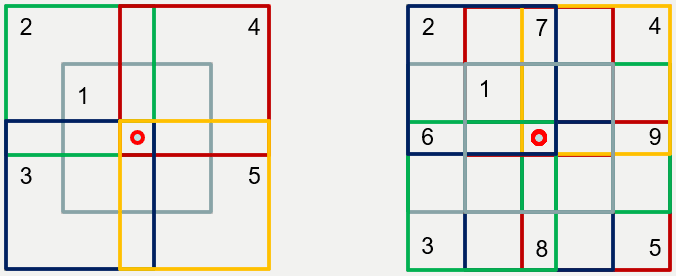
Figure 2: 5 (left) and 9 (right) overlapping windows with a pixel in the center used in the subpixel algorithm.
5.3 Disparity Map Quality: Single vs. Multiple Windows
The improvement from the multiple-window approach is clearly visible in the disparity maps below. Edges are sharper, and depth noise at object boundaries is substantially reduced. The results were received during the real-world prototype testing.
a) Standard single-window SAD
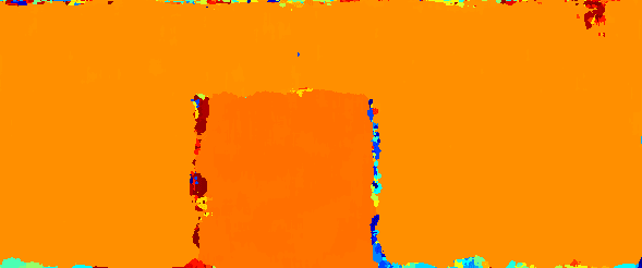
b) 5-window adaptive SAD

c) 9-window adaptive SAD

Figure 3: Disparity maps of a box at 1500 mm. Color indicates depth (the warmer the color, the closer the object). a: Standard single-window SAD shows noisy edges. b and c: The 5-window and 9-window adaptive algorithms produce sharper, cleaner edges with reduced boundary noise.
The images above are the result of the stereo cameras' image processing by the developed algorithm that was implemented in MATLAB.
A key recommendation from the project is migration to C++ or C# with multi-core and/or FPGA parallelization for real-time production use. The SAD correlation is inherently parallelizable and well-suited to FPGA implementation that allows ensuring real-time 3D-mapping with a very high accuracy.
6. Experimental Results
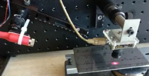
6.1 Bench-Top Setup & Test Methodology
A rigid benchtop prototype was assembled with the selected cameras, lenses, and projector. The 150 mm distance between the cameras was chosen as a baseline. Testing was conducted against known-dimension cardboard box targets at calibrated distances from 700 mm to 4000 mm. For depth accuracy validation, a precision translation stage was used to shift the object along the prototype's optical axis.
Depth accuracy was measured by computing the 3D map at distance z, then physically shifting the prototype by a known increment (e.g., 4 mm or 16 mm) and comparing the calculated distance change to the known shift. Size accuracy was measured by computing the dimensions of the box from the 3D map and comparing them to the known box dimensions.
6.2 Performance Summary
| Metric | Range | Req. | Pixel Acc. | Sub-pixel Acc. |
|---|---|---|---|---|
| Depth detection error | 700–1500 mm | ±3.5 mm | 2.2 mm ✓ | 0.9 mm ✓ |
| Depth detection error | 700–4000 mm | ±30 mm | 11.3 mm ✓ | 10.5 mm ✓ |
| Size detection error (avg) | 700–1500 mm | ±3 mm | 1.28 mm ✓ | 1.42 mm ✓ |
| Size detection error (max) | 700–1500 mm | ±3 mm | 3.9 mm ✗ | 3.8 mm ✗ |
| Size detection error (avg) | 700–4000 mm | ±7.5 mm | 7.12 mm ✓ | 15.6 mm ✗ |
| Size detection error (max) | 700–4000 mm | ±7.5 mm | 23.5 mm ✗ | 17.2 mm ✗ |
✓ = within specification · ✗ = exceeds specification · All values are worst-case across 5 repeated measurements
The system fully meets all specifications at the primary 700–1500 mm working distance. At extended range (up to 4000 mm), depth accuracy is still well within spec; size accuracy at maximum distance (4000 mm) exceeds the ±7.5 mm specification with the pixel algorithm, driven by the reduced pattern contrast at long range. Sub-pixel accuracy at 4000 mm underperforms, reflecting a known speckle-pattern artifact unique to the Osela projector. A higher-contrast projector or the laser diode coherency reduction would resolve this.
7. System Limitations & Optimization Roadmap
7.1 Known Limitations of the Bench-Top Prototype
Four limitations were identified during prototyping and testing:
- FOV mismatch: The Osela projector's 45° × 45° illumination cone is narrower than the cameras' 67.1° × 52.9° FOV, leaving uncovered regions at the image periphery that cannot contribute to the 3D map.
- Low projector contrast: The Osela projector produces lower-than-expected pattern contrast, increasing depth map noise and limiting long-range performance.
- Speckle-induced dot shape variation: The laser diode radiation creates speckle patterns whose local intensity profile varies with viewing angle. Left and right cameras see slightly different dot shapes, adding systematic correlation noise at depth discontinuities.
- Processing speed: The MATLAB prototype is not optimized for real-time operation. Production deployment requires C++/FPGA implementation.
7.2 Recommended Optimizations for Production Design
OFH identified clear engineering paths to address each limitation:
- Increase the contrast for the projected pattern. It can be made by the switching to LED pattern projectors or adding speckle-reducing elements
- Increase stereo baseline to improve depth resolution and accuracy of the size detection at extended distances
- Implement algorithm in C++, using multi-core SAD parallelization and camera binning modes for higher images processing and 3D mapping process
- FPGA parallel SAD computation (e.g., Xilinx Kintex-7 platform) for real-time depth map generation at full sensor resolution
8. Technical Significance
This project demonstrates the full breadth of OFH's capability to take a system from optical requirements through algorithm to validated hardware prototype, within a 14–16 week engagement. The key technical contributions were:
- Creation of the optical model (Zemax OpticStudio) of complete structured-light stereo system, establishing irradiance budgets, pattern density requirements, and theoretical accuracy limits before any hardware was purchased
- Derivation of the subpixel accuracy requirement from first principles and optical simulations that directly shaping the algorithm architecture decision
- Development of the multiple-window adaptive SAD algorithm for improved edge detection at depth discontinuities
- Full experimental validation of the prototype against specification requirements, and developing an optimization roadmap
From optical simulation (ZEMAX OpticStudio) through component selection, mechanical prototype, algorithm development (MATLAB), and experimental validation, OFH delivered a complete, working 3D mapping system ready for production optimization within the contracted 14–16 week timeline.
9. About Optics for Hire
Optics for Hire (OFH) is an optical engineering consultancy based in Arlington, Massachusetts, with R&D teams in the United States and Europe. Since 2002, OFH has delivered optical engineering services across more than 800 unique programs, from startup prototypes to Fortune 50 production systems.
OFH capabilities relevant to this work include ZEMAX (OpticStudio) sequential and non-sequential optical modeling, stereo and structured-light imaging system design, opto-electronic system integration, algorithm development (MATLAB, C++, OpenCV), and prototyping (design, manufacturing, and testing).
Notable related programs include:
- First commercial LiDAR lenses for autonomous vehicles — Velodyne / Google Waymo, 2006
- Depth-sensing imaging optics — PrimeSense (acquired by Apple), 2009
- Closed-loop autofocus servo systems for semiconductor wafer processing — Carl Zeiss SMS, 2024–2025
- Industrial distance measurement product — MTI Instruments
| Illumination Design | Imaging Lens Design | Electronics & Software | System Prototyping |
|---|---|---|---|
| LED & laser illumination, aviation, medical, DOE optics | Self-driving car optics, ophthalmoscopes, endoscopes, night-vision | Autofocus electronics, closed-loop motion control, FPGA, OpenCV | Laser spectrometers, VR/AR, optical metrology, 3D sensing |
Relevant Expertise
- Stereo & structured-light 3D imaging
- ZEMAX non-sequential modeling
- Computer vision algorithm development
- OpenCV / MATLAB / FPGA implementation
- Opto-mechanical prototype design
- Lens selection & optical system integration