STVZO-Compliant Bicycle Light Lens: Custom Optic Design for a Dynamo Light
Optics for Hire
491 Massachusetts Ave., Suite 206b · Arlington, MA 02474
www.opticsforhire.com · (781) 583-7810
Magniclight A European cycling technology company specializing in wheel-integrated dynamo lighting
Custom Injection-Molded Bicycle Light Lens — ZEMAX Optical Design & Prototyping
1. Executive Summary
Optics for Hire (OFH) was engaged by a European cycling technology company to design a custom injection-molded PMMA lens for a dynamo bicycle front light. The light is mounted at the rim of both wheels, harvesting energy from the rotating wheel without batteries or external wiring — with a small footprint that put constraints on optic size.
The primary challenge was achieving a beam pattern compliant with the German StVZO TA23 standard — the most demanding bicycle light regulation in Europe — using only a 20 mm diameter lens driven by a single Cree XQE-HI LED producing approximately 25–35 lumens. OFH delivered a custom lens design, validated by ZEMAX non-sequential ray-trace simulation, full CAD model, IES photometric file, and machined prototypes for physical testing.
Simulated peak illuminance: 10.67 lux at HV point (10 m) — exceeding the 10 lux minimum. Lens optical efficiency: 87%. Sharp cut-off at 5.7° above HV with < 0.02 lux above it — meeting the critical anti-glare requirement. TÜV Berlin independent measurement confirmed compliant beam distribution after minor mounting adjustments were made after prototyping.
2. Background & Design Challenge
2.1 Application Context
The client manufactures bicycle lights that generate power from the rotating wheel rim — eliminating the need for batteries or spoke-mounted dynamos. Their concept used left and right front facing lights mounted on the wheel rim. The entire optical system, including LED, lens, and housing, needed to fit within a very shallow circular envelope of no more than 20 mm diameter and approximately 11 mm height.
The client needed the front light to comply with German road traffic regulations (StVZO §67 / TA23), which specify a demanding photometric distribution requirement rarely met by products of this physical size. Competing products from other manufacturers with similar lens sizes were also observed to struggle with full TA23 compliance.
2.2 The StVZO TA23 Photometric Standard
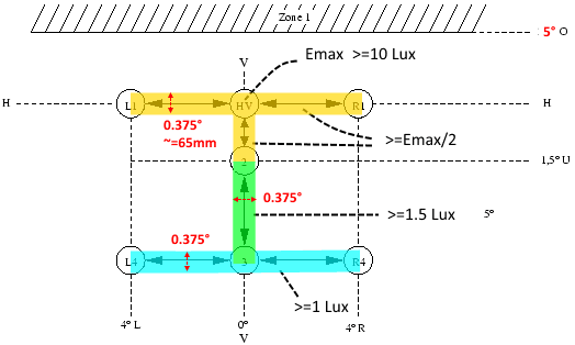
The German StVZO TA23 standard defines a precise illuminance distribution pattern measured at 10 meters working distance. The specification imposes requirements in multiple angular zones simultaneously:
- HV point (brightest point): ≥ 10 lux — located above the horizontal center line
- Zone 1 (anti-glare): ≤ 2 lux above HV — the critical cut-off requirement to avoid blinding oncoming cyclists and pedestrians
- Yellow zone (±4° wide, 1.5° below HV): ≥ 50% of peak (Emax/2) — horizontal spread requirement
- Green zone (5° below HV): ≥ 1.5 lux — road illumination close to the bicycle
- Blue zone (±8° wide): ≥ 1 lux — wide field visibility
2.3 Why This is Optically Difficult
Meeting TA23 from a 20 mm diameter lens with only ~30 lumens input is challenging for three reasons:
- Aperture limitation: Optical efficiency (lux at HV) scales approximately with lens aperture area. A 20 mm lens has roughly 1/4 the collecting area of a typical 40 mm bicycle lens — limiting peak intensity.
- Cut-off sharpness: The anti-glare Zone 1 boundary must be very sharp — less than a few degrees from the peak. Achieving a hard cut-off while maintaining wide horizontal spread requires a fundamentally different optical architecture than a standard bicycle lens.
- LED die image artifacts: The Cree XQE-HI die (1 × 1 mm) produces a non-uniform emission pattern with asymmetric corners. Any lens design that relies on forming an image of the die at the HV point must control the die orientation precisely, otherwise off-axis bright spots violate the Zone 1 limit.
3. Optical Design Approach
3.1 Dual-Zone Lens Architecture
After evaluating multiple design strategies — including round symmetric lenses, lenses with wave/diffuser surface features, and reflector-based approaches — OFH developed a dual-function asymmetric lens architecture specifically for this application.
The key insight driving the final design is that a single lens must simultaneously perform two distinct optical functions:
- The outer/side surface of the lens collects and redirects light to create the bright HV line — the horizontally elongated peak intensity region required by TA23.
- The central inner surface features produce the wider, dimmer LED footprint image that fills the green and blue illuminance zones below HV.
3.2 Asymmetric Lens Shape
A critical design evolution was transitioning from a rotationally symmetric lens to an asymmetric profile — one side slightly wider (20 mm) and the other slightly narrower (18 mm). This asymmetry serves two purposes: it creates the necessary beam asymmetry to push the HV concentration upward relative to the LED die image, and it establishes a defined orientation reference for LED placement on the PCB.
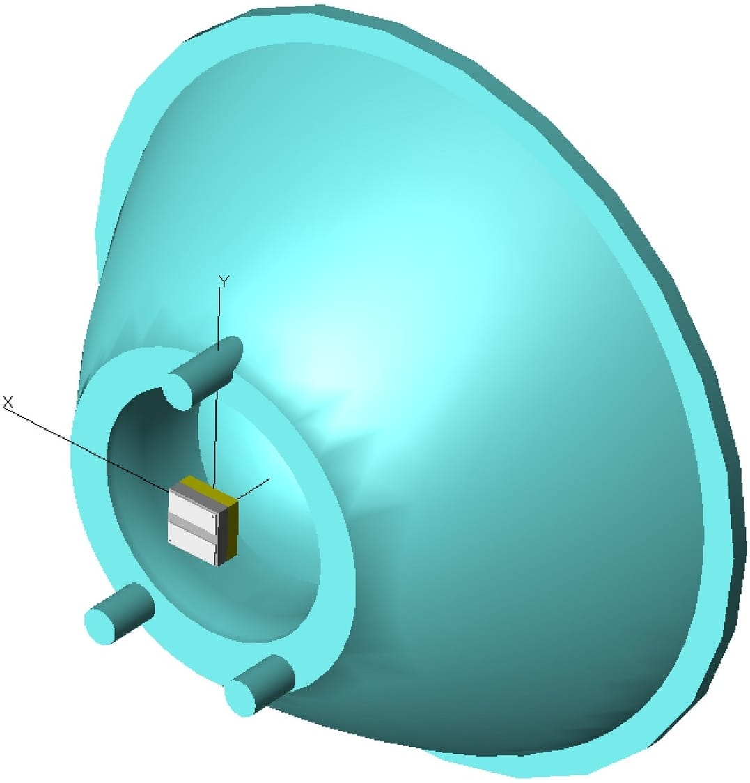
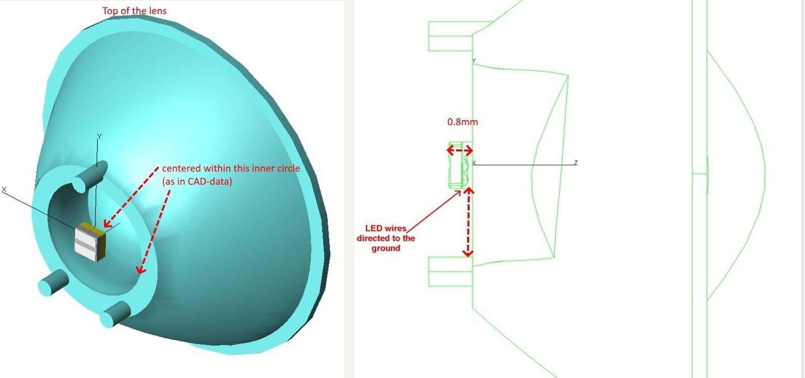
The final lens geometry — asymmetric outer profile with inner surface features, no diffuser waves on the front face — fits within a 20 mm mounting envelope, is 11 mm tall, uses PMMA V825 material, and incorporates a front flange (1.4 mm thick to accommodate the injection gate) plus three mounting pins for PCB registration.
3.3 LED Selection and Orientation
LED selection was critical to achieving the design goals within the 20 mm aperture constraint. OFH specified the Cree XQE-HI (High Intensity variant, part # XQEAWT-H0-0000-00000LFE1), which has a 1 × 1 mm die — significantly smaller than the XQE-HD (High Density) or XD16 (1.6 × 1.6 mm die). The smaller die size reduces the angular extent of the LED image at the detector, allowing more light to be concentrated within the narrow HV zone.
A key discovery during design was that the LED die has slightly asymmetric corner metallization — when oriented at 0°, this produces a split HV pattern with two slightly separated bright points. Rotating the LED 90° about its axis resolves this into a clean, uniform bright line at HV. This finding was incorporated as a manufacturing specification.
4. ZEMAX Simulation Results
4.1 Simulated Beam Performance
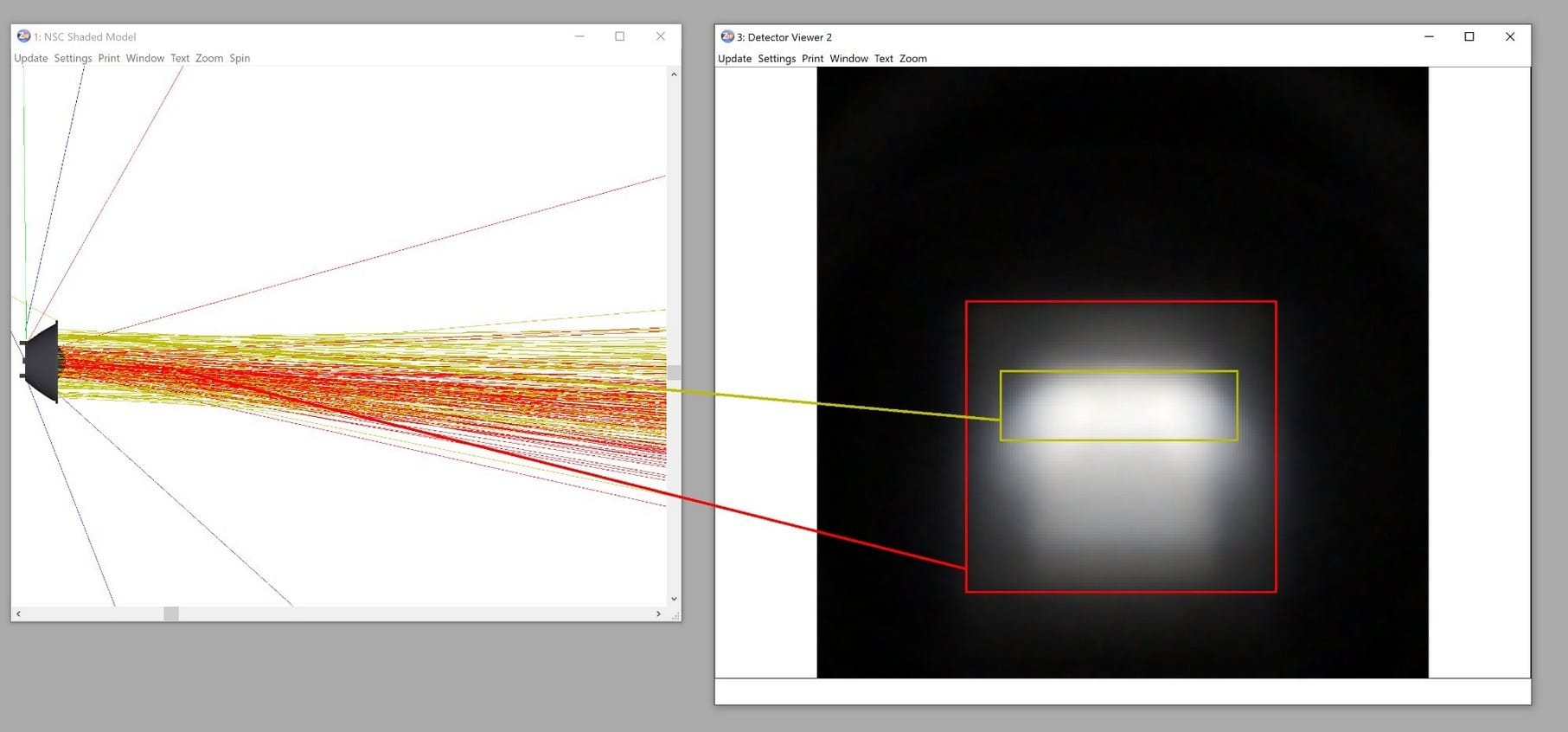
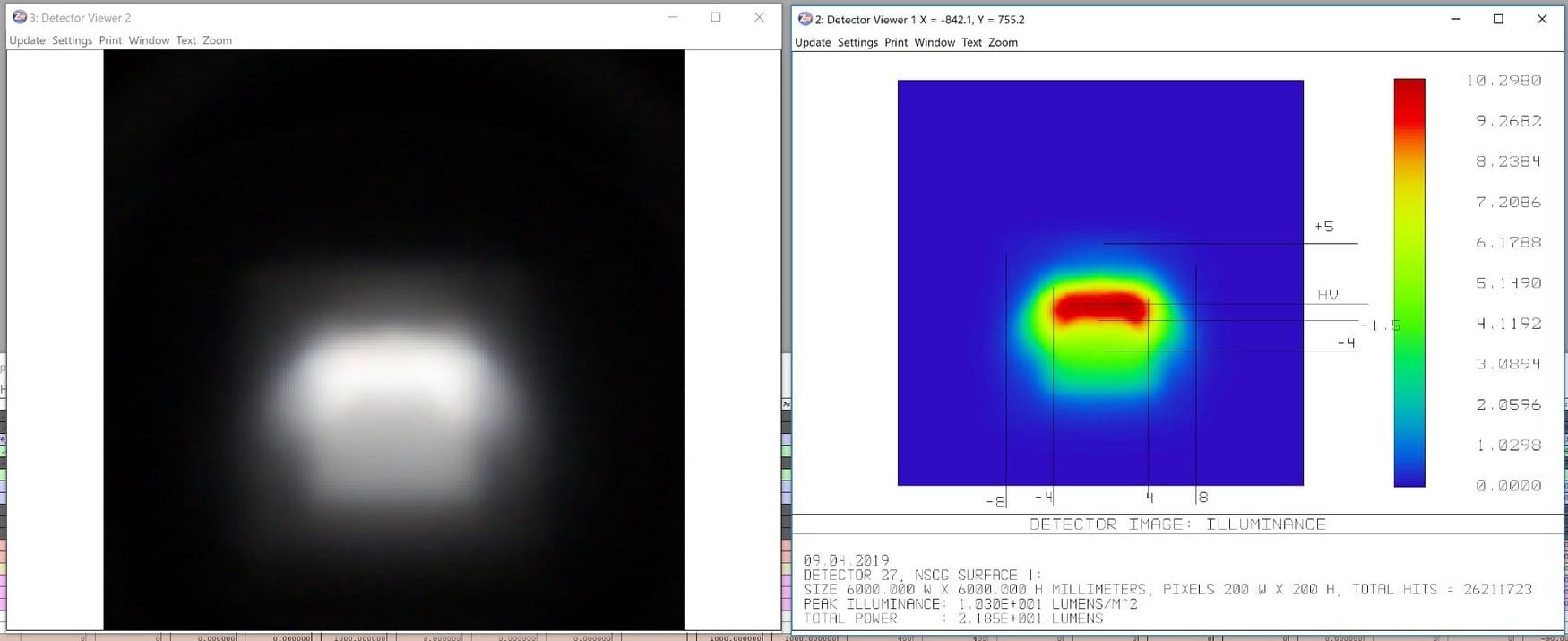
The final lens design was simulated in ZEMAX non-sequential ray-trace mode using the Cree XQE-HI LED photometric model at 25–30 lumens. The simulation correctly models both the bright HV line (formed by the outer lens surfaces) and the wider, dimmer LED footprint image (formed by the inner features), producing a realistic composite beam pattern on a virtual detector at 10 meters.
| Parameter | Value / Notes |
|---|---|
| LED source | Cree XQE-HI, XQEAWT-H0-0000-00000LFE1 |
| LED flux (simulation) | 25–30 lumens |
| Lens diameter | 20 mm (18 mm narrow side, asymmetric) |
| Lens height | 11 mm |
| Lens material | PMMA V825 |
| LED-to-lens distance | 0.802 mm |
| LED orientation | 90° rotated from standard — wires to ground |
| Lens efficiency | 87% |
| Peak illuminance (HV) | 10.67 lux at 10 m (StVZO minimum: 10 lux) ✓ |
| Cut-off above HV | 5.7° with < 0.02 lux above (StVZO max: ≤ 2 lux in Zone 1) ✓ |
| Zone above 3.2°–5° | 1.7 lux (StVZO limit: ≤ 2 lux) ✓ |
| Below HV (5°) | ~3 lux (StVZO minimum: ≥ 1.5 lux) ✓ |
| Tolerance (LED position) | ± 0.1 mm lateral, ± 1° tilt |
Simulation confirms the design meets all StVZO TA23 requirements by design: ≥10 lux at HV, ≤2 lux in Zone 1, and adequate illuminance in all required angular zones. The 87% lens efficiency is high for a custom PMMA optic of this complexity.
4.2 LED-to-Lens Alignment Sensitivity
A key contribution of the simulation work was characterizing how sensitive the beam pattern is to LED positioning errors — information essential for setting manufacturing tolerances. OFH computed beam patterns for a matrix of lateral (X, Y) and axial (Z) displacements:
- Lateral shift ≥ 0.2–0.3 mm in Y (vertical): HV line shifts noticeably, Zone 1 boundary deteriorates
- Lateral shift ≤ 0.1 mm: beam remains within specification
- Axial shift: less sensitive than lateral — ±0.1 mm has minimal effect
- Tilt: relatively insensitive to small tilts (1–2°)
These simulations directly informed the manufacturing tolerance specification of ±0.1 mm lateral positioning — confirmed to be achievable by precision PCB manufacturing — and the recommendation to use machine-placed rather than hand-soldered LED assembly.
5. Lens Orientation & Manufacturing Documentation
A complete manufacturer's documentation package was delivered, including the STEP CAD file, tolerance drawings, LED orientation specification, and an IES photometric data file enabling the client to simulate the complete product in Dialux or similar lighting design software.
6. Prototyping & Physical Testing
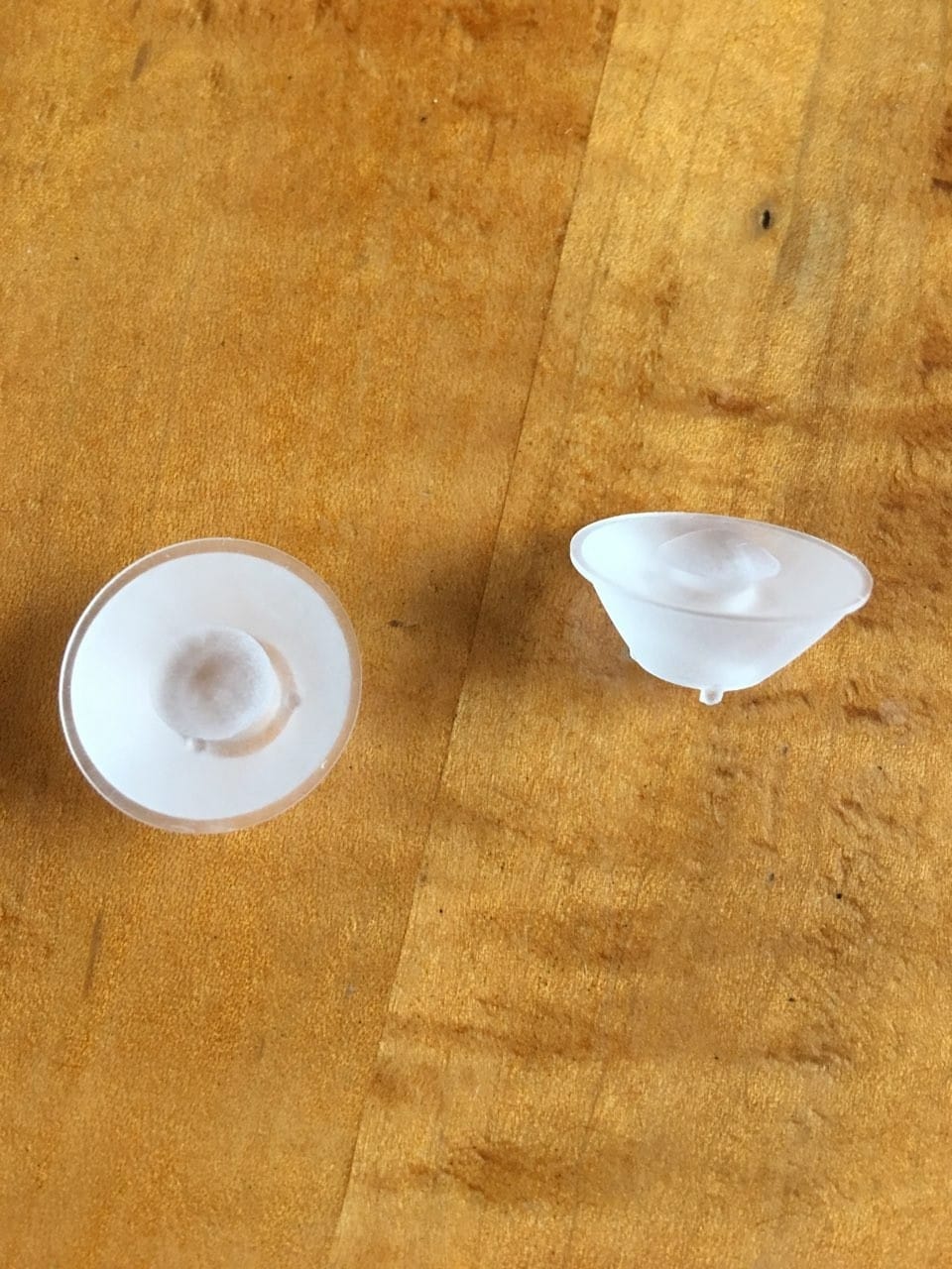
6.1 Machined PMMA Prototypes
OFH arranged machined and hand-polished PMMA prototype lenses through an established manufacturing partner. Two samples were produced. Machined/polished prototypes are inherently less efficient than injection-molded parts: surface roughness from the machining process scatters light that would otherwise be transmitted, typically reducing peak illuminance by 30–40% compared to a molded lens.
6.2 Prototype Testing & Findings
Physical testing of the machined prototypes revealed a key mounting sensitivity that was not fully apparent from simulations alone: the LED-to-lens axial distance needed to be 0.25 mm less than specified in the initial mechanical design. Independent measurements by the client's partner testing laboratory confirmed this finding — when the corrected distance was used, the measured beam pattern was very close to the ZEMAX simulation.
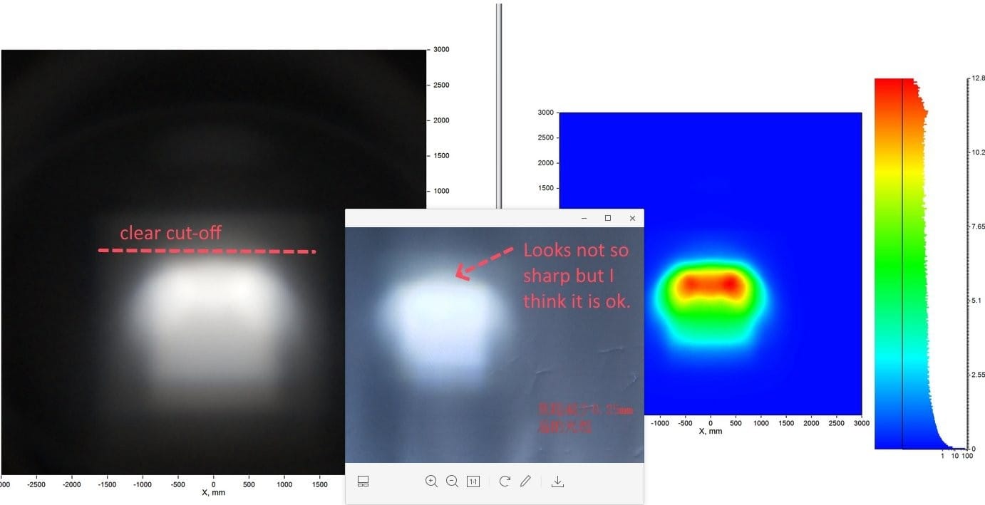
Additional prototype testing by OFH's own optical team confirmed two further findings: the bright HV line is clearly present and can be isolated by blocking the central lens area with opaque tape, and the remaining mismatch between prototype and simulation is due to inadequate surface polish on the machined part — the inner and side surfaces require higher polish quality than was achieved in the first prototype batch.
The prototype testing program revealed that machined prototypes are useful for confirming beam pattern shape but not for quantitative lux validation. The molded lens — with its superior surface quality and tighter geometric tolerances (±0.02 mm from LEDLink) — is expected to match or exceed the simulated performance. The 0.25 mm axial offset correction was incorporated into the final mold specification.
7. Injection Mold Production & TÜV Testing
7.1 Mold Production
Following prototype validation, the client proceeded with injection mold tooling through a precision optics molder, achieving ±0.02 mm dimensional tolerances — five times tighter than the initial prototype machining. This tolerance level is consistent with OFH's simulation findings that ±0.1 mm lateral positioning is required for full specification compliance.
During mold development, one manufacturing change was evaluated: increasing the front flange thickness from 0.5 mm to 1.4 mm to accommodate the injection gate position without interfering with the O-ring seal. OFH simulated this change and confirmed it reduces peak illuminance by less than 2% — a negligible optical penalty for a significant manufacturing simplification.
7.2 TÜV Berlin Independent Measurement
The complete system was submitted to TÜV Berlin for independent StVZO measurement. The TÜV report confirmed that the beam pattern is very close to specification compliance — the distribution shape matches the design intent well. The measured result fell just outside the Zone 1 boundary requirement, with the brightest point approximately 4.5° rather than the required ≤3.4° from the Zone 1 limit.
Post-measurement investigation by the client team identified that a small vertical adjustment to the LED mounting position shifts the complete beam pattern upward, placing the HV point at the correct angular position relative to Zone 1. This finding is consistent with the simulated sensitivity analysis — a 0.2–0.3 mm vertical LED shift produces the observed effect. Separate PCB boards for left and right lights (rather than a shared flipped board) were specified to maintain correct LED orientation on both sides.
The TÜV measurement result, combined with the LED position adjustment finding, indicates that full StVZO compliance is achievable with a minor PCB design modification — confirming the optical design was sound.
8. Project Summary
This effort worked at the limits of what is physically achievable from a 20 mm bicycle optic meeting regulatory beam pattern compliance. The principal technical contributions of the OFH design work were:
- Development of a dual-zone asymmetric lens architecture that simultaneously achieves a sharp anti-glare cut-off and wide horizontal spread from a single small-diameter PMMA optic.
- Identification and characterization of LED die orientation effects on beam symmetry — a subtle but practically important finding that became a defined manufacturing requirement.
- Quantitative tolerance sensitivity analysis (lateral, axial, tilt) informing PCB manufacturing specifications and confirming ±0.1 mm as the critical tolerance.
- Complete prototype-to-mold development cycle with OFH-arranged prototype sourcing, physical testing at OFH's facility, and simulation-based root cause analysis of prototype deviations.
- Delivery of production-ready documentation including STEP CAD, tolerance drawings, LED orientation spec, and IES photometric file.
From initial concept through ZEMAX non-sequential simulation, tolerance analysis, CAD design, prototype sourcing, physical testing, and TÜV-level performance analysis — OFH delivered a complete end-to-end illumination optic development program for a challenging constrained-aperture application.
9. About Optics for Hire
Optics for Hire (OFH) is an optical engineering consultancy based in Arlington, Massachusetts. Since 2002, OFH has delivered optical engineering services to clients ranging from startups to Fortune 50 corporations.
OFH capabilities directly relevant to this work include illumination optic design (ZEMAX non-sequential), injection-molded lens design and tolerance analysis, LED system optimization, photometric simulation, CAD-to-prototype sourcing, and physical beam testing. Notable related programs:
- DOT street lighting optics — US Department of Transportation
- Aviation and dental headlamp illumination systems
- TIR lens design for LED illumination products
- Reflector and lens systems for medical device lighting (ophthalmoscopes, endoscopes)
- Closed-loop autofocus servo optics for semiconductor wafer processing — Carl Zeiss SMS, 2024–2025
| Illumination Design | Imaging Lens Design | Electronics & Software | System Prototyping |
|---|---|---|---|
| LED/laser illumination, TIR lenses, medical & aviation lighting, bicycle optics | Self-driving car optics, ophthalmoscopes, night-vision, objective lenses | Autofocus electronics, closed-loop motion control, LED driver boards | Laser spectrometers, VR/AR systems, optical metrology, injection-molded optics |
Project Expertise
- ZEMAX non-sequential illumination design
- Custom injection-molded lens design
- LED system optimization & selection
- StVZO / photometric standard compliance
- Tolerance sensitivity analysis
- Prototype sourcing & physical beam testing
- IES photometric file generation