Uniform High-PPFD Grow-Light Optics for Indoor Vertical Farming
Optics for Hire
491 Massachusetts Ave., Suite 208 · Arlington, MA 02474
www.opticsforhire.com · (781) 583-7810
1. Executive Summary
Optics for Hire (OFH) designed a custom two-part LED optic for an indoor vertical farming company developing supplemental grow lights for human-tended cultivation environments. The system uses an 8-LED array (2×4, Luminus CXM-22 COB modules) suspended above a 1.2 × 2.4 m planting area and must deliver high, uniform photosynthetic photon flux density (PPFD) to plants while keeping glare at safe levels for workers standing below the luminaires.
The optical design consists of a freeform mirror-coated polycarbonate reflector paired with a square Fresnel lens, both custom-designed in ZEMAX non-sequential ray tracing. The design achieves far above the minimum PPFD requirement, delivers excellent uniformity across the target grow zone at the design working distance, and was validated across multiple heights with a dedicated worker glare safety analysis.
Simulated PPFD at 70 cm working distance: ~410 µmol/m²/s — exceeding the 340 µmol/m²/s minimum requirement. Peak illuminance in the target zone exceeds 23,000 lux. Tight beam cone limits face-level glare to ~230 lux at 2 m mount height. Full production drawings, STEP CAD files, and component tolerances delivered for injection molding.
2. Background & Design Requirements
2.1 Application: Indoor Supplemental Grow Lighting
The client designs grow-light luminaires for indoor vertical farming operations where workers tend plants at close range. Unlike automated warehouse-style vertical farms, this environment requires the lights to be suspended directly above head height — creating tradeoffs between delivering high photon flux to plants and avoiding glare or photobiological hazard to workers' eyes.
A key goal was to shape the beam from a circular pattern (naturally produced by a round LED and optic) into a rectangular footprint matching the 1.2 × 2.4 m planting bed geometry. This avoids wasted light spilling beyond the grow area and reduces the risk of hotspots from overlapping circular beams when multiple fixtures are tiled.
2.2 System Requirements
| Parameter | Requirement |
|---|---|
| LED source | Luminus CXM-22 COB Array, 4000K, 80 CRI |
| Array layout | 2×4 LEDs, 60 cm spacing between units |
| Total illuminated area | 1.2 × 2.4 m (matches 2×4 array footprint at 60 cm pitch) |
| Working distance (optic to plant) | 70 cm (design target) |
| Minimum PPFD at plant level | 340 µmol/m²/s |
| Beam shape | Rectangular, matching grow bed — avoid circular hotspots |
| Glare safety | Minimize direct glare exposure for standing workers |
| Optic material — lens | Makrolon LED 5102 (clear polycarbonate, Covestro) |
| Optic material — reflector | Polycarbonate with mirror coating |
| Deliverables | ZEMAX simulation, CAD (STEP), production drawings with tolerances |
3. Design Approach
3.1 Why a Reflector + Fresnel Lens Combination
OFH evaluated several optical architectures before arriving at the final design. The key constraint ruling out simpler approaches was the requirement for a rectangular beam pattern combined with glare-free performance.
- TIR (total internal reflection) lenses alone: explored first, including lenslet array variants to attempt rectangular beam shaping. While TIR lenses are highly efficient, achieving a true rectangular spot from a round COB LED with a TIR element proved incompatible with the glare constraint — TIR surfaces can direct significant high-angle light toward workers' eyes.
- Diffuse reflector material (Makrolon RW2407): rejected. The diffuse polycarbonate spreads light over too wide an angle, reducing intensity at the target plane and making it impossible to control the beam boundary.
- Projection lens system: evaluated but considered too complex and optically inefficient for a production luminaire.
- Reflector + Fresnel lens: selected. The mirror-coated reflector captures and redirects the wide-angle LED emission into a controlled cone, while the Fresnel lens collimates and shapes the output into a near-rectangular footprint. The reflector geometry also naturally shields workers from direct line-of-sight to the LED, addressing the glare requirement.
Round optics inherently produce round beams. A freeform reflector profile — with scalloped, lobed sidewalls rather than a simple parabolic or elliptical cross-section — is the key innovation that reshapes the beam footprint toward a rectangle to match the 1.2 × 2.4 m grow bed.
3.2 Material Selection
The lens material, Makrolon LED 5102, is a Covestro optical-grade polycarbonate specifically optimized for LED optic applications. It offers high transmittance in the PAR (photosynthetically active radiation) range of 400–700 nm, good resistance to UV-induced yellowing, and is suitable for injection molding to the tight tolerances required for a Fresnel lens. The reflector uses a general polycarbonate substrate with a mirror coating deposited on the reflective surface. The originally specified RW2407 diffuse material was replaced during the design process once ZEMAX analysis confirmed it would not provide adequate beam control.
4. Optical Design
4.1 Component 1: Freeform Mirror-Coated Reflector
The reflector is a square polycarbonate body with a central aperture that mounts over the LED package. The reflective inner surface uses a freeform profile with scalloped lobes rather than a rotationally symmetric geometry. This asymmetry is the mechanism by which a rectangular beam footprint is produced from a round LED source — different lobe curvatures along the long and short axes of the fixture control beam divergence independently in each plane, allowing the 1.2 m × 2.4 m aspect ratio to be achieved.
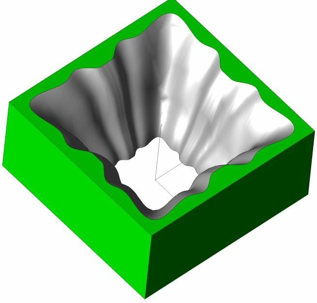
Figure 1: ZEMAX CAD model of the freeform mirror-coated reflector. The scalloped, multi-lobe inner surface profile redirects wide-angle LED emission while shaping the output toward a rectangular beam pattern. The reflector body is polycarbonate with a mirror coating on the optical surface. Central aperture fits over the Luminus CXM-22 COB LED package.
4.2 Component 2: Square Fresnel Lens
The Fresnel lens is a square flat-profile lens (70 × 70 mm footprint, 38.32 mm total assembly height) molded from clear Makrolon LED 5102 polycarbonate. The concentric Fresnel zones are visible on the top surface; the square outer boundary — rather than a circular aperture — contributes to the rectangular beam shaping by filling the corners of the illuminated zone that a circular lens would leave dark. The lens sits directly on top of the reflector body, with the LED-to-lens optical distance set by the reflector geometry.
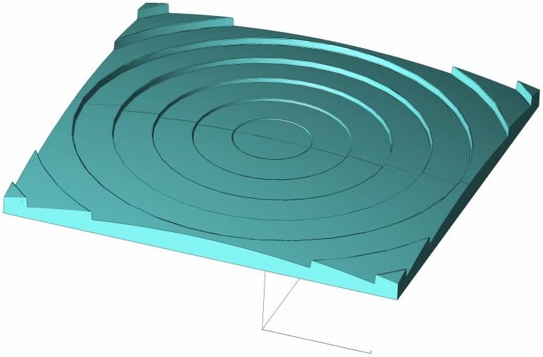
Figure 2: ZEMAX CAD model of the square Fresnel lens (70 × 70 mm, Makrolon LED 5102 polycarbonate). The concentric Fresnel zones on the upper surface collimate and shape the output from the reflector. The square boundary — rather than circular — helps fill the corners of the rectangular illuminated footprint. Alignment tabs visible at the edges locate the lens on the reflector body.
4.3 System Assembly
In the assembled optic, the Fresnel lens rests on the reflector body, which in turn mounts over the LED. The final mechanical design will add mounting features, LED positioning pins, and thermal management interfaces; the optical design phase delivers the bare optical surfaces and their relative positions. The 70 mm square footprint of the lens defines the overall luminaire optic size.
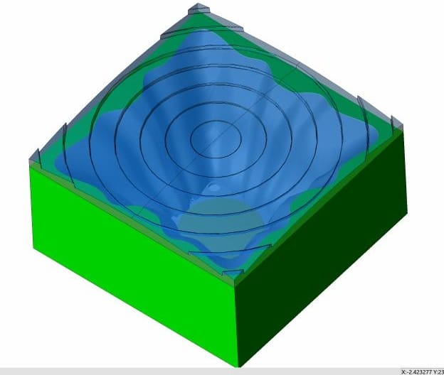
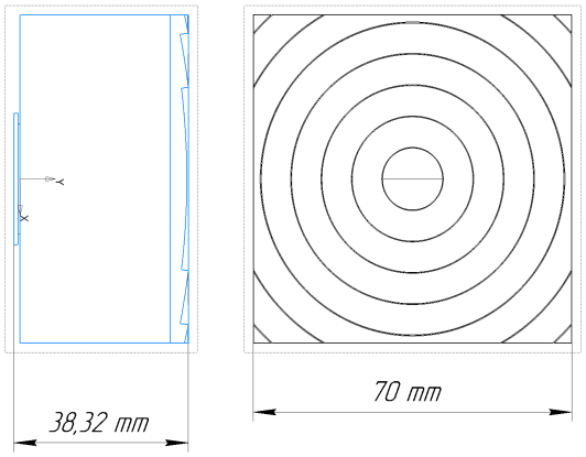
Figure 3: Left — ZEMAX assembly model showing the Fresnel lens (blue/teal) seated on the freeform reflector body (green). Right — Engineering drawing showing system dimensions: 38.32 mm total height (side view) and 70 × 70 mm footprint (top view with Fresnel zone pattern visible).
5. ZEMAX Non-Sequential Simulation
5.1 LED Source Model & Array Setup
The LED source model for the Luminus CXM-22 was obtained directly from Luminus Devices and imported into ZEMAX OpticStudio as a non-sequential source object. Each LED was modeled at 1.11 A drive current, corresponding to 9,200 lumens output. Optical losses through the reflector and Fresnel lens surfaces were included in the simulation. The full 2×4 array (8 units, 60 cm pitch) was modeled to evaluate combined illuminance and PPFD across the 1.2 × 2.4 m target plane.
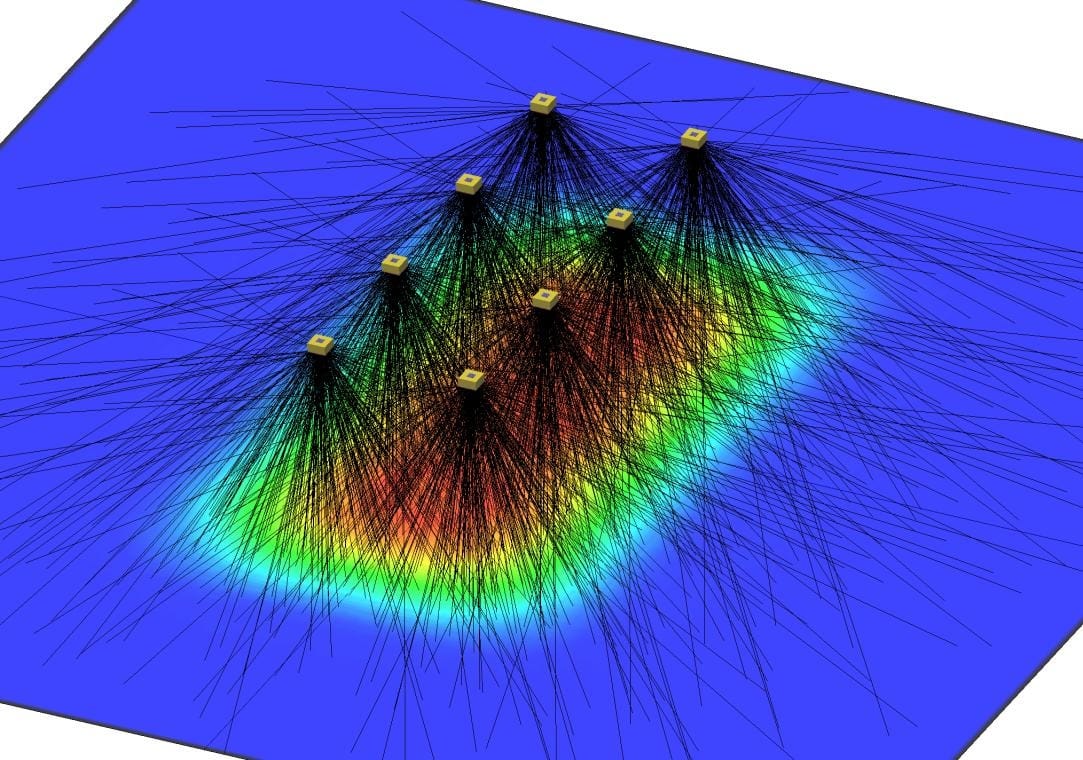
Figure 4: ZEMAX non-sequential ray trace of the full 2×4 LED array. Gold cubes represent the eight Luminus CXM-22 COB modules. Ray colors indicate intensity (false color: red = high, blue = low). The beams from adjacent units overlap and merge at the target plane 70 cm below, producing a continuous illuminated rectangle rather than eight separate spots.
5.2 PPFD and Illuminance at Target Distance
At the design working distance of 70 cm, the combined 2×4 array produces a simulated PPFD of approximately 410 µmol/m²/s across the 1.2 × 2.4 m target area — exceeding the 340 µmol/m²/s minimum requirement by 20%. Peak illuminance within the target rectangle exceeds 23,000 lux (verified against a Waveform Lighting LUX-to-PPFD conversion tool for 4000K spectrum), with good uniformity across the central grow zone.
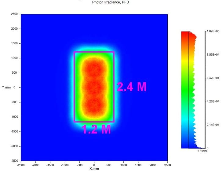
Figure 5: Simulated photon flux density (PFD / PPFD) map from the 2×4 array at 70 cm working distance. The magenta rectangle marks the 1.2 × 2.4 m target grow area. The beam fills the required rectangle with the highest flux concentrated in the central zone and gradual roll-off toward the edges. Peak PFD ~107,000 (normalized units) corresponds to ~410 µmol/m²/s.
5.3 Illuminance vs. Height — Multi-Plane Analysis
A key deliverable from the design review was illuminance maps at multiple heights between the luminaire and the plant canopy, to allow the client to characterize performance across different installation geometries and plant heights. OFH simulated illuminance (in lux) at six planes: 10, 30, 50, 70, 75, and 90 cm from the optic.
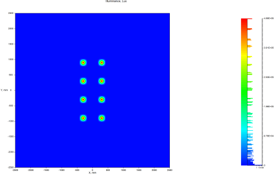
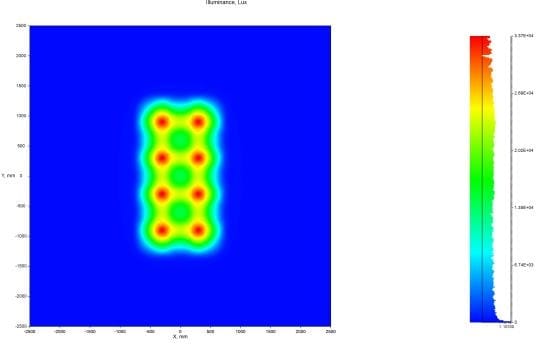
Figure 6: Illuminance maps showing beam evolution with distance. Left: 10 cm — the 8 LED spots are fully separated (individual beams visible, peak ~489,000 lux per spot). Right: 70 cm design distance — beams have merged into a continuous 1.2 × 2.4 m illuminated rectangle with good uniformity (peak ~33,700 lux across target zone).
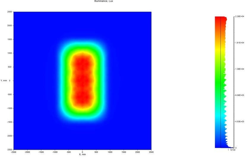
Figure 7: Illuminance at 90 cm working distance. At this height the beam has spread further and the individual LED contributions are fully blended, producing the most spatially uniform distribution. Peak illuminance ~22,600 lux. This height may be preferable for maximizing uniformity where plant canopy height or rack design permits.
| Distance from optic | Beam character | Peak illuminance (lux) | Notes |
|---|---|---|---|
| 10 cm | Fully separated spots | ~489,000 | Individual LED footprints visible |
| 30 cm | Partially merging | ~150,000 | Overlap beginning at array center |
| 50 cm | Mostly merged | ~52,000 | Rectangular shape emerging |
| 70 cm | Fully merged — target | ~33,700 | Design working distance, ≥340 µmol/m²/s |
| 75 cm | Fully merged | ~29,000 | Slightly more uniform than 70 cm |
| 90 cm | Most uniform | ~22,600 | Best uniformity; use for taller canopies |
6. Worker Glare Safety Analysis
Because the luminaires are suspended above working height in a human-tended environment, OFH performed a dedicated glare analysis as part of the design review. The client specified three mounting heights to evaluate: 2.0 m, 2.2 m, and 2.4 m above floor level, with a reference worker body height of 180 cm.
The freeform reflector geometry provides inherent glare mitigation by restricting the beam cone angle: most of the luminous output is directed downward within a tight cone toward the plant canopy. A worker standing alongside the array (not directly under it, where plants are) is primarily exposed to the side-scattered component, not the main beam.
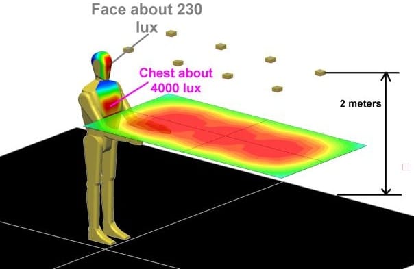
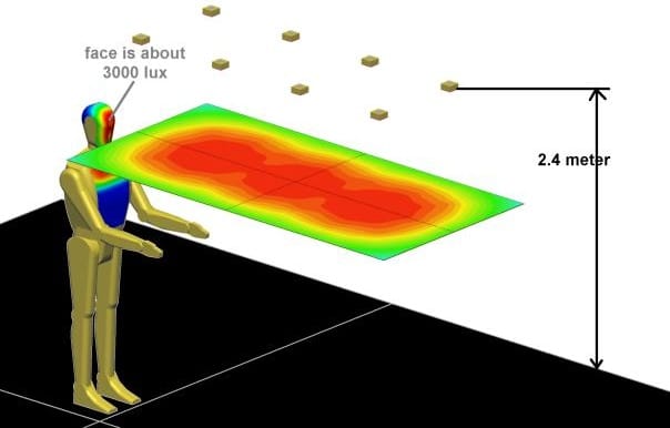
Figure 8: Worker glare analysis simulations. Left: 2.0 m mount height — face receives approximately 230 lux (comfortable; well below photobiological hazard thresholds), while chest receives ~4,000 lux in the primary beam. Right: 2.4 m mount height — face exposure further reduced as the worker's head is further below the beam cone. The tight beam cone means eye-level exposure drops rapidly with lateral distance from directly beneath a luminaire.
At 2.0 m mount height, simulated face-level illuminance is ~230 lux — a comfortable level for continuous occupancy. Chest-level illuminance (~4,000 lux) is within the primary beam zone. Workers directly below and looking upward would experience higher exposure; standard guidance applies: eyes above the luminaire plane are safe given the narrow cone. Plant canopies also provide natural shielding in practice.
7. Manufacturing Deliverables
OFH delivered a complete optical design package ready for injection mold quotation and tooling:
- ZEMAX non-sequential simulation files with full array model and illuminance/PPFD analysis at all specified heights
- STEP CAD files for both optical components (reflector body and Fresnel lens) with bare optical surfaces
- Production drawings (PDF) for the Fresnel lens and reflector with general tolerances suitable for injection molding
- Design review documentation including multi-height illuminance maps, PPFD verification, and worker glare analysis at 2.0, 2.2, and 2.4 m mounting heights
The design package was submitted to OFH's injection mold vendor for preliminary pricing review. The Fresnel lens is molded from clear Makrolon LED 5102 polycarbonate; the reflector uses a polycarbonate base with mirror coating applied post-molding. Follow-on mechanical design phases added mounting features, LED thermal interface geometry, and assembly alignment features to the optical shells.
The design was prototyped and tested with OFH support and the system was successfully launched to the client's customers.
8. Technical Significance
This project demonstrates several capabilities that are particularly relevant for horticultural and architectural lighting applications:
- Freeform reflector design for rectangular beam shaping: moving beyond rotationally symmetric optics to match real-world grow bed geometries, eliminating wasted light and reducing tile hotspots.
- Non-sequential ZEMAX illumination modeling: full system ray tracing including realistic LED source files, optical losses, and multi-unit array superposition to predict actual PPFD and uniformity at the plant plane.
- Multi-height simulation: characterizing illuminance across a range of working distances, enabling the client to specify optimal mounting heights for different cultivation scenarios.
- Worker safety integration: glare analysis embedded in the optical design workflow — not as an afterthought — allowing the system to be verified for human-safe operation before tooling.
- Injection-mold-ready deliverables: production drawings and STEP files delivered alongside simulation results, shortening the path from optical design to prototype hardware.
9. About Optics for Hire
Optics for Hire (OFH) is an optical engineering consultancy based in Arlington, Massachusetts, serving clients from startups to Fortune 50 corporations since 2002. Our team includes physicists, optics PhDs, and mechanical, electrical, and software engineers with deep expertise in both imaging and illumination system design.
OFH capabilities directly relevant to horticultural, architectural, and industrial lighting include:
- ZEMAX non-sequential ray tracing for illumination and photometric analysis
- Freeform reflector, TIR lens, light pipe, and Fresnel lens design — over 500 illumination optics designed
- Custom DLL and macro development to accelerate illumination system optimization
- Rectangular and asymmetric beam shaping for area lighting applications
- PPFD / photobiological metrics for horticultural lighting
- Injection-mold-ready optical drawings and STEP CAD delivery
- LED source modeling from manufacturer IES/ray files
| Illumination Design | Imaging Optics | Electronics & Software | System Integration |
|---|---|---|---|
| TIR lenses, reflectors, Fresnel lenses, light pipes — 500+ custom designs | Surgical cameras, machine vision, NIR/fluorescence, objective lenses | LED drivers, autofocus electronics, laser spectrometer signal processing | VR/AR optics, medical devices, grow lighting, architectural & industrial luminaires |
Relevant Expertise
- ZEMAX non-sequential illumination design
- Freeform reflector & TIR lens design
- Fresnel lens design for LED systems
- Rectangular / asymmetric beam shaping
- PPFD & photobiological metric analysis
- Worker glare safety evaluation
- Injection-mold-ready optical drawings