Downhole Optical Fluid Discrimination Sensor: Optical Modeling for High Temperature High Pressure Oilfield Sensor
Optics for Hire
491 Massachusetts Ave, Suite 206b · Arlington, MA 02474
www.opticsforhire.com · (781) 583-7810
1. Executive Summary
Optics for Hire (OFH) was engaged by a Fortune 500 oilfield services and industrial technology company to develop a ZEMAX non-sequential optical model of a downhole fiber-optic fluid discrimination sensor. Operating in high-temperature, high-pressure (HTHP) environments, the sensor tip needed to reliably distinguish between oil, gas, and water by exploiting differences in refractive index and fluorescence emission. OFH built two independent ZEMAX simulation approaches — one based on a CAD-imported geometry and one using parametric ZEMAX macro surfaces — which cross-validated to within 9% of each other, confirming model accuracy and delivering a robust design toolkit for the client's sensor optimization program.
Two independent ZEMAX models cross-validated: fluorescence collection efficiency η = 0.0299–0.0326 (reference geometry). Cone angle has minimal impact on efficiency across 80°–120°. Maximum collection efficiency achieved at minimum sensor tip height and minimum outer radius — providing clear design guidance for the client's manufacturing program.
2. Background & Design Challenge
Downhole formation fluid sampling is critical to oilfield reservoir characterization. The sensor must discriminate between three fluid phases — gas, water, and crude oil — in real time at temperatures exceeding 175°C and pressures above 20,000 psi. Optical methods are preferred over electrochemical approaches because they are passive, chemically inert, and can be multiplexed along a fiber bundle.
In addition to the harsh environmental requirements, important constraints included a system architecture with no moving parts, the ability to work remotely at long distances without degradation of the optical signal, and good resistance to radiation and electromagnetic interference.
The sensing modalities under investigation were:
- Total Internal Reflection (TIR): Fluid RI < tip RI → light reflects back into fiber. Fluid RI > tip RI → light leaks out. Gas: n = 1.00–1.20; Water: n = 1.33–1.38; Oil: n = 1.45–1.70.
- Attenuated Total Reflection (ATR): Absorption of the evanescent field at the tip surface enables fluid composition analysis.
- UV-Excited Fluorescence: Crude oil fluoresces strongly at 700–800 nm when excited at ~400 nm. Gas and water do not. Fluorescence intensity is a direct indicator of oil presence.
The primary challenge for OFH was to quantify fluorescence collection efficiency as a function of sensor tip geometry — specifically the cone half-angle, tip height, and outer radius — and to validate the simulation results against a second independent modeling approach.
3. Sensor Tip Geometry & Materials
The sensor tip is a shaped glass or sapphire element bonded to the end of a fiber bundle. The geometry is approximately conical or hemispherical, with the following key parameters:
| Parameter | Value / Range |
|---|---|
| Tip materials | Sapphire (n = 1.74), HOYA/SCHOTT specialty glass (n = 1.54–1.62) |
| Fluid RI — Gas | n = 1.00 – 1.20 |
| Fluid RI — Water | n = 1.33 – 1.38 |
| Fluid RI — Oil | n = 1.45 – 1.70 |
| Excitation wavelength | ~400 nm (UV LED or laser) |
| Fluorescence emission | 700–800 nm (crude oil) |
| Cone half-angle | 40°–60° (full angle 80°–120°) |
| Operating environment | HTHP: T > 175°C, P > 20,000 psi |
4. ZEMAX Modeling Approach — Method 1: CAD Import
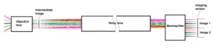
The first modeling approach used a SolidWorks-generated shell of the sensor tip geometry imported into ZEMAX Non-Sequential as a luminous surface. The fluorescence emission was modeled as a Lambertian source distributed uniformly over the tip surface at 750 nm. Ray tracing was performed with 10⁶ rays to capture the statistical distribution of collected fluorescence power at the fiber bundle face.
Key steps in the CAD-import method:
- SolidWorks parametric model of cone tip exported as STEP/STL
- ZEMAX NSC object imported, material properties assigned (glass RI at 750 nm)
- Fluorescence source: Lambertian emission at 750 nm applied to tip outer surface
- Detector: annular fiber bundle face at proximal end of tip
- Fluorescence collection efficiency η = P_collected / P_emitted computed from ray trace
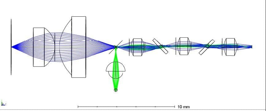
Figure 1: ZEMAX non-sequential model — CAD-import method. The sensor tip (center) is illuminated by UV excitation (blue rays). Fluorescence emission (red/orange rays) from the conical tip surface is captured by the fiber bundle face at the proximal end. The outer cone geometry and material RI determine collection efficiency.
5. ZEMAX Modeling Approach — Method 2: Parametric Macro Surfaces
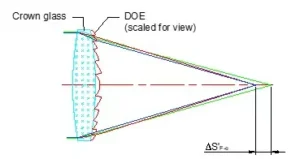
The second approach constructed the sensor tip geometry entirely within ZEMAX using parametric surface definitions and a custom ZEMAX macro. This method allowed rapid sweep of geometric parameters (cone angle, height H, outer radius R2) without requiring a new CAD export for each configuration.
The parametric model used:
- ZEMAX User-Defined Surface (UDS) for the conical tip profile
- Macro-driven parameter sweeps across cone angles (80°, 90°, 100°, 110°, 120°) and tip dimensions
- Identical source and detector definitions to Method 1 for direct comparison
- Batch execution of ray traces to generate η vs. geometry lookup tables

Figure 2: ZEMAX parametric macro model. Tip geometry is defined analytically via surface equations, enabling rapid parameter sweeps without CAD re-import. Ray trace shown for 100° full cone angle. Collection efficiency is computed as the ratio of rays arriving at the fiber face to total emitted rays.
6. Cross-Validation & Key Results
The reference geometry (baseline cone angle and dimensions) was modeled by both methods and results compared:
| Metric | Method 1 (CAD Import) | Method 2 (Parametric) | Agreement |
|---|---|---|---|
| Collection efficiency η (reference) | 0.0326 | 0.0299 | < 9% difference ✓ |
| Cone angle sensitivity (80°–120°) | Low — η varies < 15% | Low — η varies < 12% | Consistent ✓ |
| η vs. tip height H | Monotonically increases as H decreases | Same trend | Consistent ✓ |
| η vs. outer radius R2 | Monotonically increases as R2 decreases | Same trend | Consistent ✓ |
The cross-validation confirmed that both models are self-consistent and that the simulation uncertainty is within an acceptable range for design guidance. The key engineering findings were:
- Cone angle has relatively small influence on fluorescence collection efficiency across the 80°–120° range — the client has flexibility in cone geometry without significant efficiency penalty.
- Shorter tip height (smaller H) increases collection efficiency — the tip should be as compact as possible consistent with mechanical constraints.
- Smaller outer radius (R2) also increases efficiency — tighter geometry concentrates fluorescence into the fiber bundle.
- The TIR sensing modality is well-separated for gas vs. water vs. oil: the sapphire tip (n = 1.74) creates TIR for all three fluid types, while lower-RI glass tips (n = 1.54) can be tuned to distinguish water from oil.
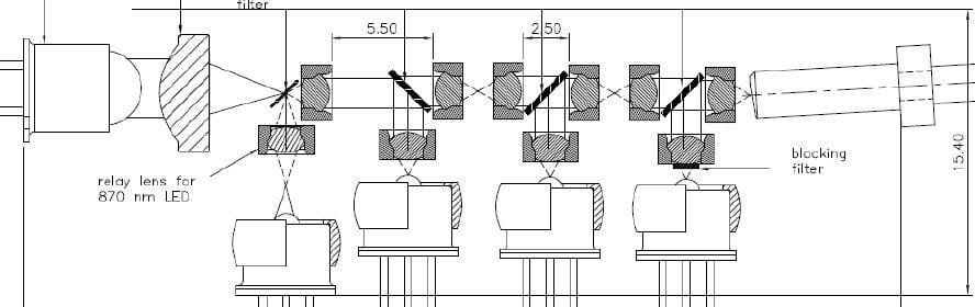
Figure 3: Collection efficiency η as a function of cone half-angle (parametric model). Each curve represents a different tip height H. Efficiency decreases with increasing H and is relatively insensitive to cone angle for angles between 80° and 120°. Maximum efficiency is achieved at minimum H.
The weak dependence of fluorescence collection efficiency on cone angle (< 15% variation across 80°–120°) simplifies manufacturing: the cone geometry can be chosen for mechanical robustness and ease of fabrication without significantly compromising optical performance. Design optimization should focus on minimizing tip height H and outer radius R2.
7. Sensing Modality Integration
The final sensor design integrates all three sensing modalities in a single tip:
- TIR/ATR sensing: Interrogating wavelength delivered via central fiber core; reflected/transmitted power monitored by adjacent fiber channels.
- Fluorescence excitation: ~400 nm delivered via dedicated UV-transmitting fiber; emission collected at 700–800 nm by outer annular fiber bundle.
- Spectral separation: Dichroic filter at fiber bundle proximal face separates UV excitation from red/NIR fluorescence emission.
The ZEMAX model outputs — specifically the angular distribution of collected fluorescence and the sensitivity to tip geometry — directly informed the fiber bundle numerical aperture specification and the physical layout of excitation vs. collection fibers.
8. Technical Significance
This project demonstrated OFH's capability to deliver complex, high-assurance optical simulation for a challenging sensing application in an extreme environment. Principal technical contributions:
- Development and validation of two independent ZEMAX non-sequential fluorescence models, cross-validated to < 9% — providing high confidence in the simulation output for a safety-critical downhole sensor.
- Parametric sweep capability enabling rapid exploration of tip geometry space (cone angle, height, radius) without requiring iterative CAD re-export — accelerating the client's design optimization cycle.
- Quantification of the relative influence of each geometric parameter on collection efficiency, providing clear design priorities: minimize H and R2, cone angle is a secondary concern.
- Integration of TIR, ATR, and fluorescence physics into a unified optical model, enabling the client to evaluate multi-modality sensing from a single simulation framework.
- Delivery of simulation results as look-up tables enabling the client's systems engineering team to select optimal tip dimensions for their production sensor.
From requirements capture through dual-method ZEMAX non-sequential fluorescence modeling, cross-validation, and parametric geometry sweeps — OFH delivered a complete simulation toolkit enabling a Fortune 500 oilfield company to optimize a novel fiber-optic downhole sensor with confidence.
9. About Optics for Hire
Optics for Hire (OFH) is an optical engineering consultancy based in Arlington, Massachusetts. Since 2002, OFH has delivered optical engineering services to clients ranging from startups to Fortune 50 corporations. Our R&D team of 12 physicists, optics PhDs, and engineers has worked on over 800 unique optical system programs.
OFH capabilities directly relevant to this work include:
- ZEMAX non-sequential optical modeling (illumination, fluorescence, scattering)
- Fiber-optic sensor design and numerical aperture optimization
- TIR/ATR/fluorescence multi-modality sensing system analysis
- High-temperature, high-pressure optical system design
- Parametric geometry sweeps and sensitivity analysis
- Cross-validation of independent optical simulation models
| Illumination Design | Imaging Lens Design | Electronics & Software | System Prototyping |
|---|---|---|---|
| LED/laser illumination, TIR lenses, medical & aviation lighting, fiber sensors | Self-driving car optics, ophthalmoscopes, night-vision, objective lenses | Autofocus electronics, closed-loop motion control, LED driver boards | Laser spectrometers, VR/AR systems, optical metrology, injection-molded optics |
Project Expertise
- ZEMAX non-sequential fluorescence & scattering modeling
- Fiber-optic sensor tip design & RI discrimination
- TIR / ATR / fluorescence multi-modality integration
- HTHP-compatible optical material selection
- Parametric design sweep & sensitivity analysis
- Custom ZEMAX macro development
- Downhole instrumentation optical systems