Resonant Actuator & 2D Beam-Steering Scanner for a Portable Optical Coherence Tomography (OCT) Platform
Optics for Hire, Inc.
491 Massachusetts Ave., Suite 208, Arlington, MA 02474
www.opticsforhire.com · (781) 583-7810
1. Executive Summary
A medical imaging technology company developing a portable optical coherence tomography (OCT) platform needed two custom electromagnetically-driven optical components that no off-the-shelf part could satisfy: a resonant 1D actuator to modulate optical path length inside a sub-20 mm envelope, and a 2D angular scanner to steer a beam across a wide field at speeds up to 50 Hz. Both needed to hold parasitic mirror tilt to a few arc-seconds while fitting inside a handheld device.
Optics for Hire modeled seven candidate magnetic-drive topologies before selecting an axial voice-coil design, engineered a leaf-spring resonant suspension validated by finite-element modal analysis, and carried the actuator from alpha prototype through three successive production runs. When the client identified a field instability after initial deployment, OFH root-caused it and updated the design for volume manufacturing. In parallel, OFH ran a design and prototyping engagement for a 2D gimbal-mounted beam-steering scanner, including a mirror-suspension trade study and an integration study tying the scanner to OFH’s scan-lens design library.
The 1D actuator is now in its third production run with tightened stroke tolerance and reduced drive current. The 2D scanner prototype’s bench evaluation surfaced a clear, well-characterized path to improved static positioning performance, discussed in Section 6.
Delivered three successive production runs of a custom resonant actuator (6, 7, then 20 units) — cutting drive current from 100 mA to 50 mA and tightening stroke tolerance to ±4 µm — while holding parasitic angular deflection below 10 arc-seconds throughout, inside a 16 × 16 × 18 mm envelope.
2. Background & Challenge
Portable OCT systems depend on two precision beam-steering functions that are difficult to satisfy simultaneously: modulating the reference-arm optical path length at a stable mechanical resonance, and steering the sample beam across a 2D field with enough angular range and speed for real-time imaging. Both functions had to fit inside a device envelope small enough to be handheld or benchtop-portable — ruling out the larger galvanometer and piezo-stack actuators typically used for these functions in laboratory OCT systems.
For the path-modulation function, the client needed a resonant actuator inside a 16 × 16 × 18 mm envelope, with a tunable resonant frequency in the 280–350 Hz range, oscillation amplitude on the order of tens of microns, and parasitic angular deflection of the reflected beam held below 10 arc-seconds — tight enough that a poorly designed suspension or an asymmetric magnetic circuit would directly degrade image quality. No catalog voice-coil actuator met this combination of size, tunability, and angular purity.
For the beam-steering function, the client needed a single-mirror 2D scanner capable of ±10° optical deflection on each axis, operating up to 50 Hz on one axis and 20 Hz on the other, inside a 25 × 25 × 20 mm envelope — a footprint far smaller than commercial 2-axis galvanometer scanners. This required a custom electromagnetic drive, a purpose-built mirror suspension, and integrated position sensing, all engineered from scratch.
3. Phase 1: 1D Resonant Actuator for Optical Path Modulation
The path-modulation actuator drives a small mirror in a linear, sinusoidal motion at mechanical resonance to sweep the OCT reference arm’s optical path length. OFH’s scope covered the full arc from electromagnetic and mechanical design through volume-manufacturable production documentation.
3.1 Magnetic Circuit Design & Trade Study
OFH modeled seven candidate magnetic-drive topologies across two design classes — axial voice-coil drives (the class used in loudspeakers and earphones) and tangential drives (the class used for hard-disk head positioning) — quantifying the useful axial force and the parasitic transverse force for each. Every topology used identical coil wire and equivalent total ampere-turns so the comparison isolated the effect of magnetic-circuit geometry alone.
| Type | Topology | Useful Force | Parasitic Force | Notes |
|---|---|---|---|---|
| 1 | Axial voice coil — flanged core, 2 coils | 7.6 × 10⁻³ N | 8.2% | Simplest, most robust to build |
| 2 | Axial voice coil — bar conductor, 2 coils | 1.16 × 10⁻² N | 5% | Tighter fastening tolerances required |
| 3 | Axial voice coil — bar + 2 field concentrators | 1.45 × 10⁻² N | 0.5% | Highest force in class; complex build |
| 4 | Axial voice coil — bar + flange + 1 concentrator | 1.15 × 10⁻² N | 4% | Selected: best size / manufacturability trade-off |
| 5 | Tangential — single magnet | 1.28 × 10⁻¹ N | 34% | Highest raw force; asymmetry unacceptable |
| 6 | Tangential — 2 symmetric magnets | 2.29 × 10⁻² N | 0.05% | Best force purity; force too low |
| 7 | Tangential — symmetric, rectangular coil | 3.43 × 10⁻² N | 0.1% | +50% force vs. Type 6, excellent purity |
OFH selected Type 4 — an axial bar-and-flange conductor with a single field concentrator — for the production design. It cut parasitic transverse force from 8.2% (the simplest flanged design) to 4%, while staying within the 16 × 16 × 18 mm envelope and avoiding the tight fastening tolerances that made the higher-purity bar-conductor designs (Types 2 and 3) harder to manufacture. A follow-on magnetic field simulation of the selected topology confirmed the design point: peak core flux density of 7.84 T, an axial drive force of 9.08 mN, and transverse parasitic forces below 10⁻⁴ N — roughly three orders of magnitude smaller than the useful force.
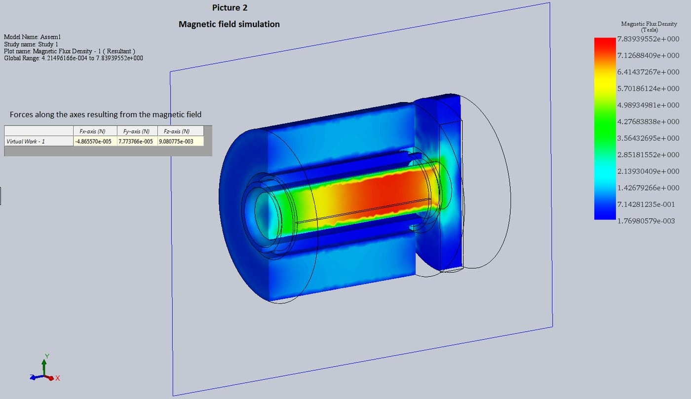
Figure 1: Magnetic field simulation of the selected drive topology. Peak flux density in the central magnetic core reaches 7.84 T; the computed axial (useful) force is 9.08 mN against transverse parasitic forces of order 10⁻⁴–10⁻⁵ N — confirming the low cross-axis coupling the trade study predicted.
3.2 Suspension Design & Modal Analysis
The moving mirror and coil assembly are guided by a parallelogram suspension of two matched beryllium-copper leaf springs, chosen over more complex flexure geometries for its combination of clean single-axis guiding, well-controlled resonant frequency, and manufacturability. A finite-element modal analysis of the spring-and-coil assembly confirmed the design before cutting production tooling.
| Mode | Frequency | Character |
|---|---|---|
| 1 | 289.2 Hz | Working mode — piston motion along the drive axis |
| 2 | 4,572.5 Hz | Parasitic — 16× the working frequency |
| 3 | 5,842.7 Hz | Parasitic |
| 4 | 8,905.8 Hz | Parasitic |
| 5 | 9,331.7 Hz | Parasitic |
The working mode sits more than 15× below the next mechanical mode, giving the actuator a wide, clean operating band with no risk of a nearby parasitic mode coupling into the drive axis — a common failure mode in miniature resonant actuators that this design avoids by a comfortable margin.
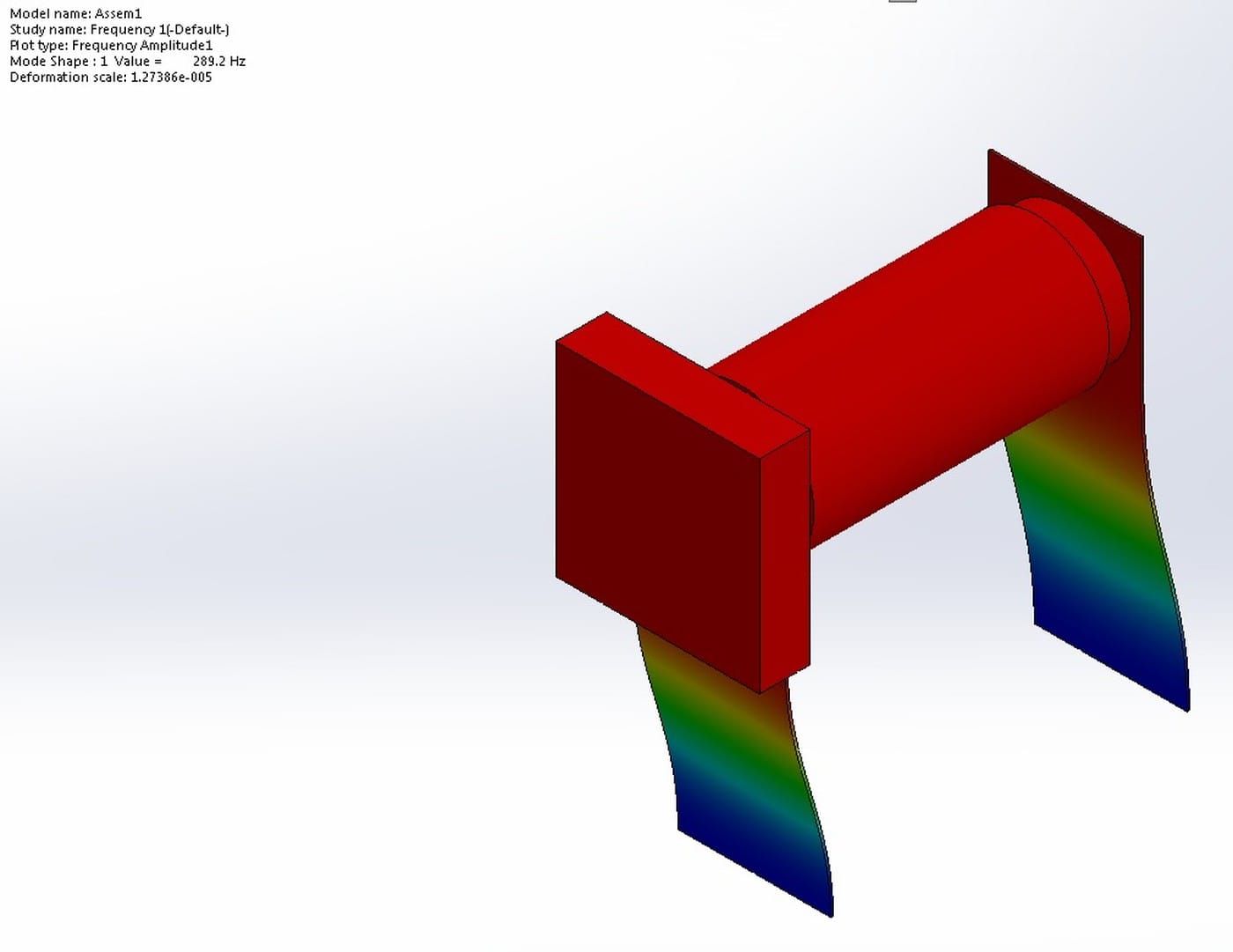
Figure 2: Finite-element modal analysis, Mode 1 (289.2 Hz) — the intended piston-motion working mode of the leaf-spring suspension.
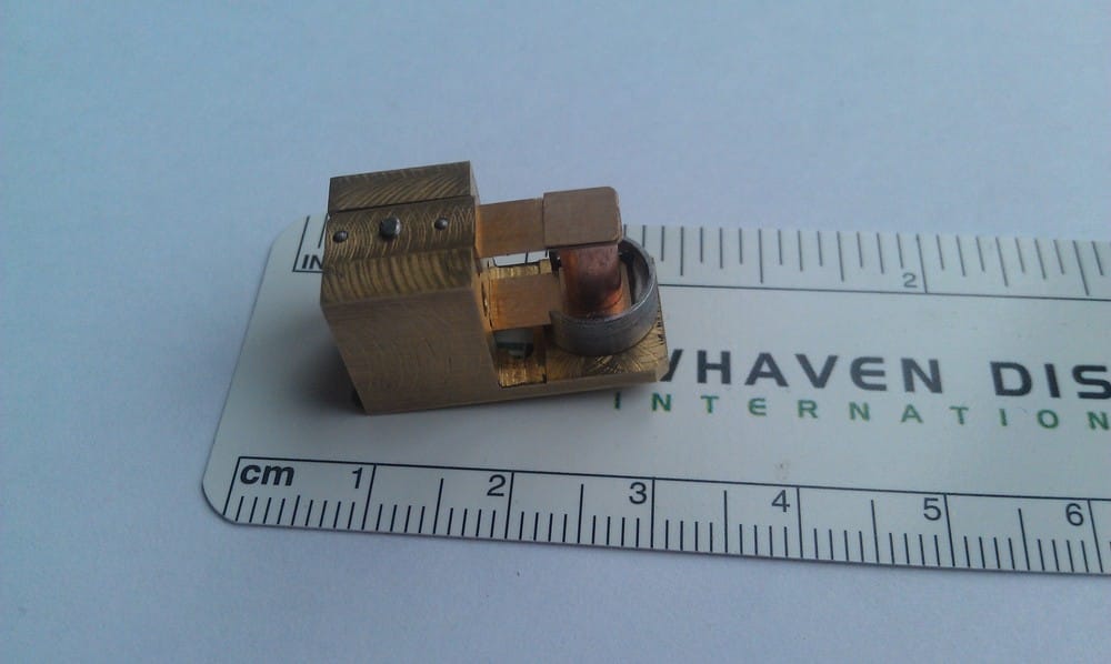
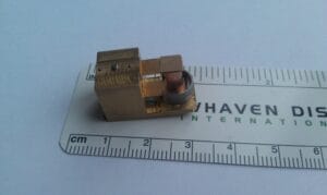
Figure 3: Assembled 1D actuator prototype shown against a metric scale. The complete drive — magnet, coil, and leaf-spring suspension — fits inside roughly a 2 cm envelope.
3.3 Alpha Prototype Iteration
Following the design phase, OFH built a first alpha prototype and shipped a second set of parts and assembly instructions so the client could build a second unit independently — a deliberate test of build repeatability outside OFH’s own shop. Bench testing on the client’s OCT setup found that the first unit exhibited turn-on hysteresis and a phase shift in its resonant response that the second, independently assembled unit did not show. The client requested the first unit be returned for rework, drawing on spare parts already on hand for several more actuators.
The episode was a useful early signal rather than a setback: it surfaced a unit-to-unit consistency issue while only two prototypes existed, at a point where rework was a parts-and-labor fix rather than a redesign, and it confirmed the assembly was repeatable enough for a client engineer — not just OFH’s own technicians — to build a working unit from the documentation alone. That repeatability carried directly into the production runs that followed.
A first-article unit showed turn-on hysteresis and a resonant phase shift that a second, independently assembled unit did not — isolating the issue to assembly variation rather than the underlying design, and confirming the build documentation was repeatable enough for the client’s own engineers to execute.
The reworked unit then went through a focused verification protocol before returning to the client:
- Frequency response sweep (200–340 Hz at 50 mA) to confirm a single, clean resonance peak — 282 Hz at 385.7 µm peak-to-peak, consistent with the isolated working mode the modal analysis predicted in Section 3.2.
- Linearity check across a 10× current range (34–345 mA), showing oscillation amplitude tracking drive current closely from 14 µm up to 150 µm peak-to-peak, with no sign of magnetic saturation.
- Safe-current margin test: the maximum usable drive current is set per unit as the highest current at which no high-frequency disturbance appears at resonance — the signature of the moving coil contacting a fixed part at large amplitude. On this unit that limit corresponded to 380 µm peak-to-peak, roughly 9× the actuator’s production working stroke of 42 µm (Section 4).
- Residual angular deviation: at the most demanding condition tested — resonance (282 Hz) at ~300 µm amplitude — toggling the drive on and off shifted the reflected spot on a screen 4 m away by less than the eye could resolve (roughly 2–3 mm, against a ~20 mm spot diameter at that range) — a simple field check consistent with the instrumented arc-second-level parasitic deflection spec.
- Low-frequency (0.5 Hz) visual inspection at 50 mA, used as a quick check for contamination in the magnetic gap: the coil moved smoothly through its full stroke with no jumps or sticking points.
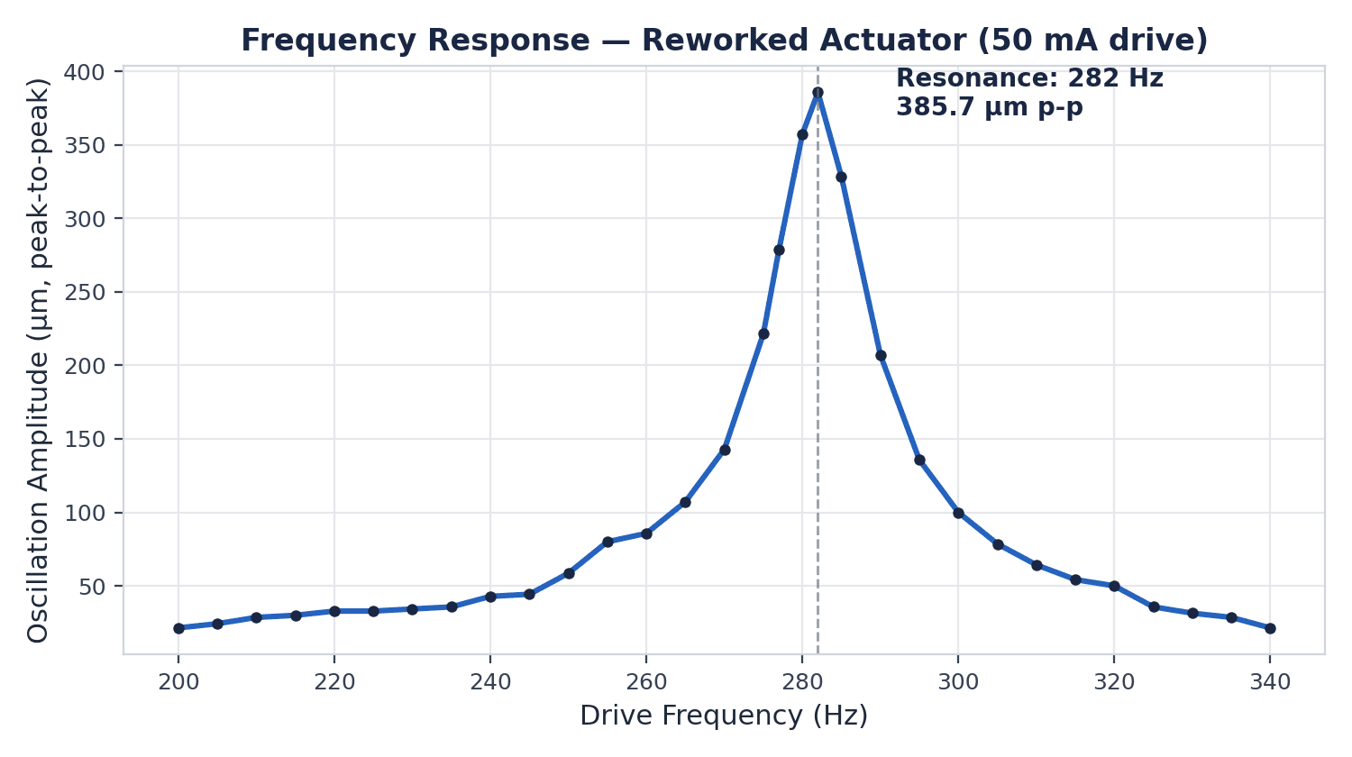
Figure 4: Measured frequency response of the reworked actuator (50 mA drive), showing a single sharp resonance at 282 Hz — the same clean, isolated-mode behavior the finite-element modal analysis predicted.
3.4 Resonant Frequency Tuning
The suspension’s leaf-spring working length is adjustable via a pressure plate and adjustment screws (visible in the cross-section drawing below), giving the actuator a tunable resonant frequency without a hardware redesign. OFH characterized the trade space between resonant frequency, drive current, oscillation amplitude, and mirror angular deviation across the tuning range:
| Resonant Frequency | Drive Current | Oscillation Amplitude (p-p) | Mirror Angular Deviation |
|---|---|---|---|
| 367 Hz | 50 mA | 298 µm | ~6 arc-min |
| 381 Hz | 90 mA | 100 µm | ~2.8 arc-min |
| 456 Hz | 150 mA* | 38 µm | not visually resolvable |
* At 456 Hz the coil runs hot at 150 mA, so this operating point trades thermal margin for the lowest angular deviation. The data gave the client a clear basis to select an operating frequency against their own thermal and drive-electronics constraints, rather than a single fixed design point.
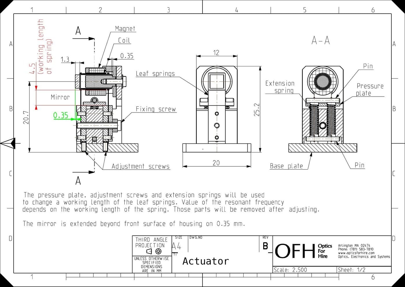
Figure 5: Cross-section engineering drawing of the production actuator. The pressure plate, adjustment screws, and extension springs tune the leaf springs’ working length — and with it the resonant frequency — before being removed for final assembly. Overall envelope: 20 mm wide × 25.2 mm tall.
Production units were characterized against this same tuning curve. Two units sampled from a later production batch resonated at 305 Hz and 304 Hz respectively — a 1 Hz spread — with matching peak stroke of 257 µm peak-to-peak, confirming the tuning process holds unit-to-unit consistency at production scale.
3.5 Production Scale-Up
With the design validated on the bench, the actuator moved through three successive production releases, each building directly on the manufacturing documentation and tooling from the last:
| Phase | Deliverable | Notes |
|---|---|---|
| Design & alpha prototyping (2016) | 2 alpha prototype units + manufacturing documentation | Bench validation on client OCT setup |
| Production run 1 (2018) | 6 units | Mechanical size 16 × 16 × 18 mm; parasitic deflection < 10 arc-sec |
| Production run 2 (2018) | 7 units | Same specification; repeat order |
| Design update & production run 3 (2019) | 20 units | Root-cause fix + tightened tolerances (Section 4) |
Each unit shipped with a test report confirming its resonant frequency, stroke, and coil resistance against specification — the same measurement protocol used during development, carried through into a repeatable acceptance test for production.
4. Manufacturing & Production Support
After the first production units were deployed in the client’s system, the client identified operating instabilities and asked OFH to investigate root cause ahead of a larger production commitment. OFH assembled a test setup that reproduced the actuator’s real operating conditions, built and instrumented units specifically for the investigation, and traced the instability to how tightly the initial design depended on driving the actuator exactly at its mechanical resonance.
4.1 Resonant vs. Non-Resonant Operation
Before committing to a fix, OFH prepared a formal trade study comparing two ways to drive the actuator, and presented both options to the client rather than defaulting to one:
| Operating Mode | Advantages | Drawbacks |
|---|---|---|
| Resonant (at peak) | ~10× lower power draw; frequency stability; amplitude set by the actuator’s own sharp mechanical response rather than drift-prone drive electronics | Requires precise resonant-frequency tuning — best achievable manufacturing tolerance is ±12–15 Hz; needs an integrated mirror-position sensor |
| Non-resonant (off-peak) | Simpler manufacturing tolerances; no fine resonance-tuning step; lower unit cost | Frequency stability fully dependent on drive electronics; amplitude less stable (operating on the response curve’s slope) — needs precision position sensing and servo if amplitude stability is critical; higher power consumption |
The client selected non-resonant operation for the updated design: the ±12–15 Hz tuning tolerance achievable in manufacturing left more unit-to-unit resonant-frequency scatter than the system could absorb while running at the peak of the response curve, and the field instability traced back to exactly that sensitivity. Moving the operating point off-resonance trades resonant operation’s power efficiency and self-stabilizing amplitude for a design far less sensitive to precisely where each unit’s resonance actually falls — paired with a deliberately smaller 42 µm stroke target, the updated design still cut drive current in half despite the less power-efficient operating point.
OFH brought the client a quantified trade-off, not just a fix: running at resonance is roughly 10× more power-efficient, but only as good as the ±12–15 Hz resonant-frequency tuning tolerance manufacturing can hold. The field instability traced directly to that sensitivity, and moving off-resonance — not a redesign of the drive itself — is what resolved it.
4.2 Updated Production Specification
The updated design tightened stroke tolerance by roughly 4×, cut nominal drive current in half, and added an explicit optical-interface requirement — controlling the gap between the oscillating mirror and the system’s output coupler to a 100–140 µm range — while holding the parasitic angular deflection spec unchanged. The design was also qualified for volume manufacturing at a contract factory, moving the product off OFH’s own bench for the first time.
| Parameter | Initial Production (2018) | Updated Design (2019, 20-unit run) |
|---|---|---|
| Operating frequency | Tunable 280–350 Hz (resonant, ~305 Hz measured) | 307 Hz nominal, 295–320 Hz tolerance, operated off-resonance |
| Stroke | ~160 µm peak-to-peak at resonance | 42 µm peak-to-peak (38–46 µm tolerance) |
| Drive current | Up to 100 mA | 50 mA (<30 mA preferred) |
| Mirror-to-coupler spacing | Not specified | 100–140 µm, controlled |
| Parasitic angular deflection | < 10 arc-sec | < 10 arc-sec (maintained) |
| Manufacturability | Benchtop / low-volume build | Qualified for volume manufacturing at factory |
Environmental qualification was extended accordingly: the updated actuator is specified to hold performance across 15–25°C with no special temperature compensation required — consistent with shifting away from a mechanism whose behavior depends on hitting an exact resonance point.
5. Phase 2: 2D Angular Beam-Steering Scanner
In a parallel engagement, OFH designed and prototyped a single-mirror, 2-axis electromagnetic scanner to steer the OCT sample beam. The scope covered the electromagnetic drive, mirror suspension, position sensing, and manufacturing documentation for working prototypes.
5.1 Requirements & Design Approach
| Parameter | Requirement |
|---|---|
| Mirror working aperture | 6 × 9 mm (for a 5 mm 1/e² beam diameter) |
| H-axis angular range | ≥ 20° peak-to-peak (±10°) at up to 50 Hz |
| V-axis angular range | ≥ 20° peak-to-peak (±10°) at up to 20 Hz |
| Rotation center | Center of mirror reflective surface (as specified) |
| Position sensing | Angular sensors on both axes |
| Overall envelope | 25 × 25 × 20 mm (±30%) |
5.2 Mirror Suspension Trade Study: Centric vs. Eccentric Rotation
The initial requirement called for the mirror’s rotation center to sit exactly on its reflecting surface (a “centric” suspension). Mechanically, that requirement forces a symmetric gimbal that increases footprint by roughly 30%, unbalances the moving mass, and pushes magnetic drive power up to an estimated 1–1.3 W — all working against the 25 × 25 × 20 mm envelope target. OFH ran a graphical ray-trace study comparing centric rotation against a simpler “eccentric” suspension, in which the rotation center sits a fixed distance behind the mirror surface, to quantify what positioning error the simpler geometry would actually cost.
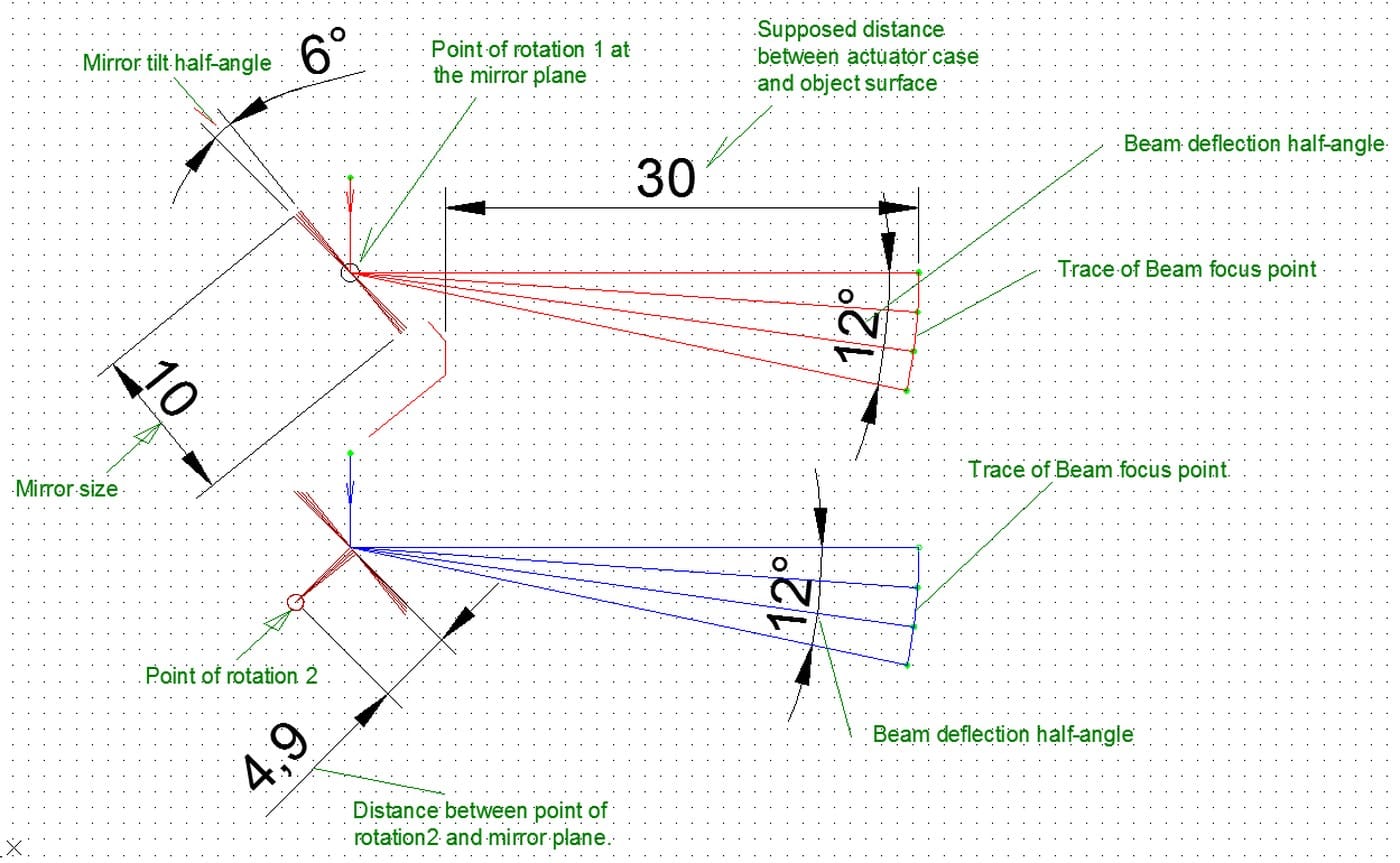
Figure 6: Graphical ray-trace comparison of centric (red) and eccentric (blue) mirror rotation, aligned at the 45° field point. At the extreme of the required ±10° deflection range, the two traces diverge by only about 0.05 mm at a 30 mm working distance — a small, quantifiable cost for a mechanically simpler suspension.
The comparison showed the positioning error introduced by eccentric rotation was small and, critically, quantifiable — giving the client a concrete number to weigh against the mechanical complexity, size, and power penalty of a fully centric gimbal, rather than defaulting to the harder mechanical solution by default. OFH carried a large-mirror gimbal concept forward for the 45° angle-of-incidence configuration actually required by the client’s optical layout.
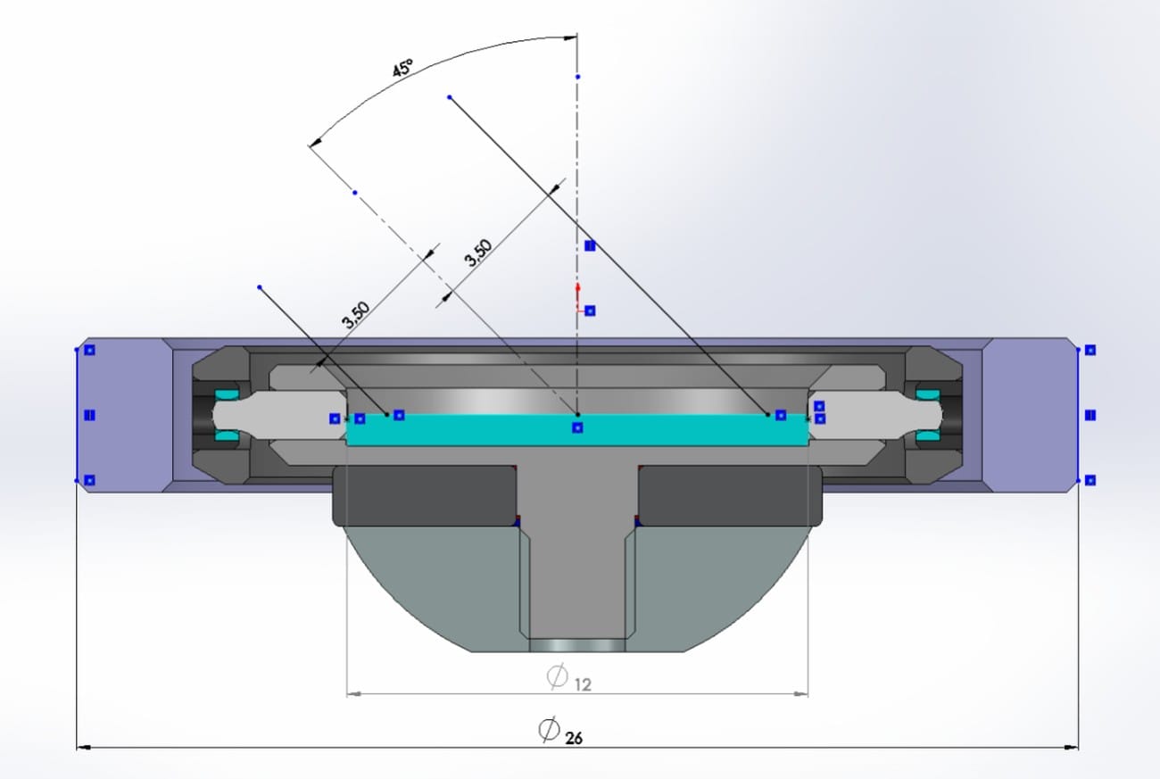
Figure 7: Concept cross-section of the gimbal mirror suspension sized for a 45° angle-of-incidence mirror mount. Case diameter is approximately 26 mm against a 12 mm mirror mount bore — close to the target envelope before the magnetic drive housing is added.
5.3 Optical Integration Considerations
Because the scanner does not operate in isolation — its mirror sits ahead of a focusing lens that images the scanned beam onto the sample — OFH evaluated the scanner’s optical requirements against its own library of F-theta scan-lens designs (including an existing OFH design with a 40 mm focal distance, 8 mm scan diameter, and telecentric ray path). Field curvature across representative F-theta designs in that library runs roughly 30–500 µm over the 24–100 mm focal-distance range typical of scan-lens applications.
Using standard Gaussian-beam theory, OFH estimated the system’s longitudinal resolution (depth of focus) at approximately 0.14 mm for a 6 mm input beam through a 50 mm focal-distance lens at a 0.8 µm wavelength — larger than the 25 µm field-curvature tolerance the client had specified. That gap indicated the field-curvature tolerance could likely be relaxed to roughly 80–100 µm without a measurable image-quality impact, easing the constraint on both the scanner and the focusing lens design.
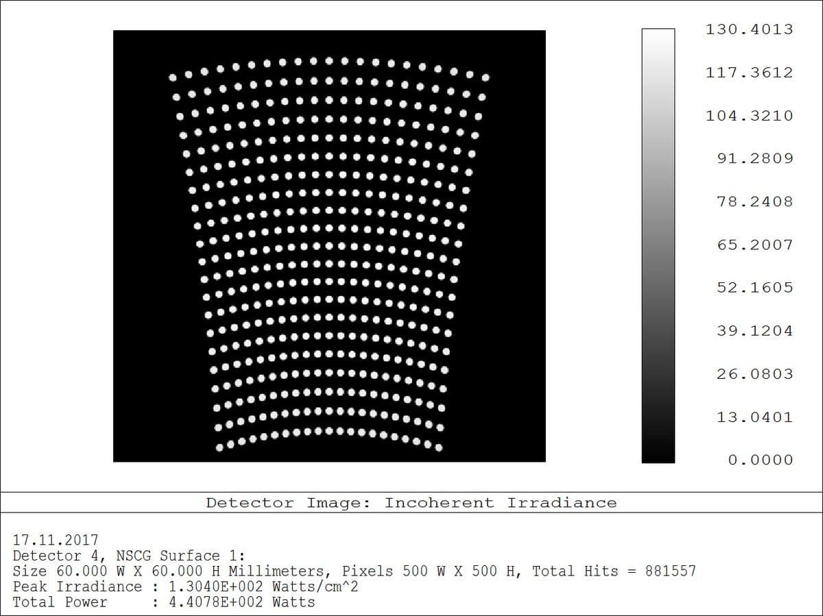
Figure 8: Non-sequential ZEMAX simulation of a projected spot grid at the scanner’s 45° working angle, showing the geometric (pincushion-type) distortion introduced by the scan geometry — the basis for a raster-distortion correction in the client’s downstream image processing.
5.4 Bench Evaluation Findings
The client bench-tested a delivered scanner prototype using a HeNe laser and a camera-based pose-tracking setup: the beam struck the scanner mirror at 45°, reflected onto a flat target screen, and a calibrated camera measured the laser-spot position as the drive voltages were swept from –3 V to +3 V in 1 V steps (with a finer 0.2 V sweep on the H-axis alone to isolate direction-dependent effects).
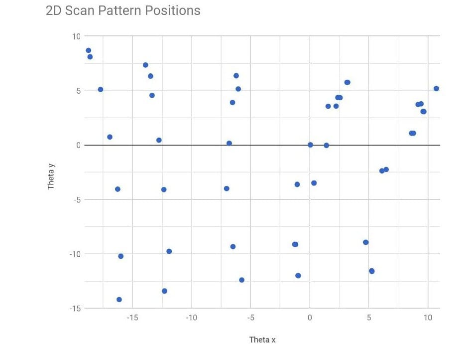
Figure 9: Measured beam-pointing grid from a 2D voltage sweep. Clustered points at the range extremes indicate positions where a 1 V drive change produced little or no angular change — consistent with static friction (“stiction”) in the mirror suspension.
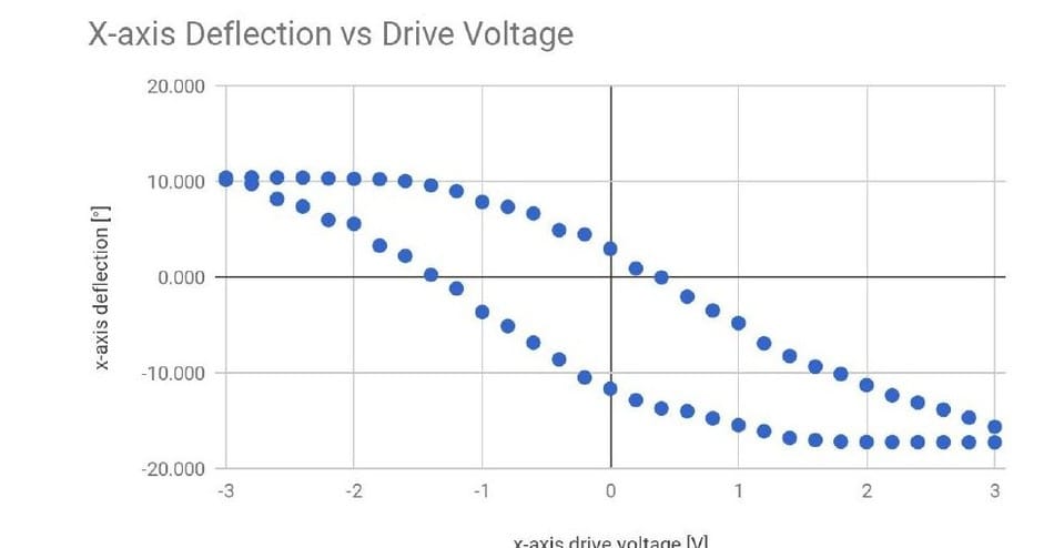
Figure 10: Bidirectional sweep of the H-axis with the V-axis held at 0 V. The two sweep directions trace clearly separated curves — several degrees of hysteresis — with a near-zero response band immediately after each direction reversal.
The built-in angular feedback sensors correlated with actual deflection but carried enough noise and cross-axis coupling that extracting a clean position signal would need dedicated compensation. Higher-frequency, dynamic operation of the scanner was visibly smoother and more predictable than slow, static (DC) positioning — the regime most of the client’s target applications actually depend on.
6. Limitations & Optimization Roadmap
The 2D scanner’s bench evaluation identified a specific, well-characterized limitation: static (DC) positioning accuracy is degraded by mechanical hysteresis and stiction in the mirror suspension, while dynamic (scanning) operation is comparatively smooth and predictable. This distinction matters because it points to a targeted fix rather than a fundamental redesign.
- Suspension refinement: a lower-friction guiding element (e.g., a flexure or bearing geometry with less sliding contact) to reduce the stiction responsible for the dead-zones observed near the range extremes.
- Closed-loop compensation: using the existing angular feedback sensors, with additional signal conditioning to reject cross-axis coupling, to actively compensate for the residual hysteresis in static-pointing applications.
- Near-term operating strategy: for applications that can tolerate it, favor dynamic (resonant or swept) scanning over slow static repositioning, where the prototype already performs predictably.
This mirrors the diagnostic path that resolved the 1D actuator’s early hysteresis finding in Section 3.3 — isolate the mechanism, quantify it, and correct it with a targeted design change rather than a ground-up redesign.
7. Technical Significance
- Quantified seven candidate magnetic-drive topologies against measured force and parasitic-force criteria before committing to a design — cutting parasitic transverse force from 8.2% to 4% of useful force in the selected axial voice-coil topology.
- Delivered a leaf-spring resonant suspension whose working mode (289.2 Hz) is isolated from the next mechanical mode by more than 15×, verified by finite-element modal analysis before cutting production tooling.
- Diagnosed and resolved a unit-to-unit hysteresis and phase-shift inconsistency during alpha prototyping, then verified the fix with a full frequency-response sweep, a linearity check, and a practical angular-deviation field test — before it could propagate into volume production.
- Root-caused a field-reported operating instability to sensitivity against the ±12–15 Hz resonant-frequency tuning tolerance achievable in manufacturing, then resolved it with a quantified resonant-vs-non-resonant trade study — cutting drive current in half and tightening stroke tolerance roughly 4× for a 20-unit production run.
- Scaled a custom electromagnetic actuator from bench prototype through three successive production releases (6, 7, and 20 units) while holding parasitic angular deflection below 10 arc-seconds throughout.
- Quantified the beam-steering error introduced by a manufacturability-driven mirror-suspension simplification (eccentric vs. centric rotation) at under 0.05 mm at a 30 mm working distance — turning a qualitative design debate into a concrete engineering trade-off.
Optics for Hire routinely designs custom electromagnetic actuators and beam-steering mechanisms from first-principles magnetic-circuit modeling through finite-element validation, prototype iteration, and volume-manufacturable production documentation — for opto-mechanical assemblies as small as a few cubic centimeters.
Related: Custom Optical Scanning & Autofocus Systems, complete systems and subsystems OFH designs and builds, including resonant mirror actuators and 2D beam scanners.
About Optics for Hire
Since 2002, Optics for Hire (Arlington, MA) has provided optical, opto-mechanical, and opto-electronic engineering services to clients ranging from start-ups to the Fortune 50. OFH helps clients invent, design, prototype, optimize, and manufacture products that emit, collect, or control light. The R&D team includes physicists, optics Ph.D.s, and electrical, mechanical, and software engineers, with offices and laboratories across three countries.
OFH is incorporated in the United States and is rigorous in protecting client intellectual property. A representative, much-abbreviated list of past program areas:
| Illumination Design | Imaging Lens Design | Electronics & Software Design | System Design & Prototyping |
|---|---|---|---|
| LED illumination optics; TIR & freeform lenses | Custom mirror & scan-lens design; F-theta lenses | Closed-loop motion control; sensor & driver electronics | Electromagnetic actuator & scanner design (this project) |
| Aviation & billboard lighting | Ophthalmoscopes, otoscopes, endoscopes | Autofocus electronics & algorithms | Optical surface & distance measurement systems |
| Grow-light & photobiological optics | Night-vision & consumer camera lenses | USB / USB2 / firewire drivers | VR / AR products |
OFH President John Ellis founded the company in 2002. He previously served as VP Marketing for the former NASDAQ-listed data-storage firm Constellation 3D, and held sales and marketing roles at several technology firms; he holds a BA from Haverford College.
Contact
Optics for Hire, Inc.
491 Massachusetts Ave., Suite 208
Arlington, MA 02474
(781) 583-7810
www.opticsforhire.com
john@opticsforhire.com
Relevant Expertise for This Project
- Magnetic-circuit modeling & electromagnetic actuator design
- Leaf-spring & flexure suspension design with FEA modal validation
- Resonant mechanism tuning & characterization
- Root-cause investigation & design-for-manufacturing updates
- Scan-lens (F-theta) design & scanner-lens system integration