When I was a young undergrad engineering student, I always found optics to be a very confusing subject. It was not only the equations, but what it looked like hundreds of different definitions involved in even the simplest of optical systems. Some concepts, like radius of curvature, f-number, and focal point were easy to understand while others, like principal plane, entendue, and Seidel’s aberrations were more complicated.
In today’s article, I want to talk about some basic definitions in optical systems, specifically, the cardinal points. If you are an experienced optical engineer, these definitions will be familiar but if you are looking to work with an optical engineer, these definitions may help you to better understand and communicate the design process.
We are going to start our definitions with the help of a thick lens. Thick lenses are those in which the lens thickness is not ignored. When working with thick lenses, we assume that the light is refracted in two different surfaces. We prefer to work with thick lenses because it gives us better results ( even if it’s more complicated than thin-lenses).

At first look, Figure 1 looks quite intimidating (at least that’s how I remember feeling back in school), but with a little bit of patience, we will describe every element in the figure.
The cardinal points help us define the image properties of an optical system. Cardinal points can be used to construct the image of an arbitrary point in space for objects in the paraxial region. The paraxial region is the region around the system’s axis of symmetry. We have three pairs of cardinal points: principal, nodal, and focal points.
Principal Planes and Principal points.
Let’s start with principal planes (the vertical lines across H1, and H2 in Figure 1). The principal planes are an hypothetical plane where we assume refraction takes place. Imagine an incident ray parallel to the optical axis that extends its path beyond the first lens surface. For a parallel incident ray, we can find the emerging ray path (which passes through the image focal point after being refracted by the second lens surface).
The rays’ path is extended until they intersect. We repeat this process for different incoming parallel rays (each at different heights) and the points of intersection are the principal planes. The principal planes are crucial in defining the system’s optical properties since it is the distance of the object and image from the front and rear principal planes that determines the system’s magnification. The principal points are the intersections of the principal plane with the optical axis.
Nodal points
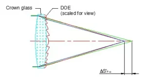
Nodal points have an interesting property in that when a light ray is incident at one of them, the refracted beam will appear to have come from the other nodal point. We can say that the nodal points define a location with unit angular magnification. They can also help us define the lens’ optical center-where the nodal ray intersects the optical axis.

Fig. 2. The optical center is where the nodal ray crosses the optical axis. FIgure from R.B Johnson
Focal Points
In an optical system, we have front and back focal points, and effective focal points, which are similar but not the same. We are going to first define what is a focal point. A focal point has a property that any ray that passes through it will emerge parallel to the optical axis once it goes through the optical system. Similarly, any ray parallel to the optical axis that passes through the optical system will converge into the focal point.
The front and back focal points (BFL1 and BFL2) are the distances along the optical axis from the surface of the lens to the focal points. The effective focal length is the distance from the nodal point to the focal point.
Vertices
The vertices, V1 and V2 in Figure 1 are the physical points at which the lens crosses the optical axis. These are measurable points that help us set the lens’ position. So, in many cases, the cardinal points use the vertices as reference points.
Final Words
Hopefully, these short explanations will help you next time in reading the description of an optical system, or if you are in the process of developing one, you can communicate better what parameters need to be corrected. If you would like for me to go through other optical definitions please let me know in the comments. I would love to hear from you.
FAQs: Cardinal Points in Optical Systems
What are cardinal points in an optical system?
Cardinal points are reference locations that describe how an optical system forms images in the paraxial region. They simplify complex systems by defining principal points, nodal points, and focal points, allowing engineers to predict magnification, image location, and angular behavior without tracing every surface.
Why are cardinal points especially useful for thick lens systems?
In thick lenses, refraction occurs at multiple surfaces, making simple thin-lens approximations inaccurate. Cardinal points provide equivalent reference locations that capture the combined effect of all surfaces, enabling accurate prediction of imaging behavior while reducing analysis complexity.
What do the principal planes represent physically?
Principal planes are hypothetical planes where refraction is assumed to occur for paraxial rays. They allow object and image distances to be measured consistently in complex systems. Magnification is determined by distances measured from these planes rather than from physical lens surfaces.
How are principal points different from principal planes?
Principal points are the intersections of the principal planes with the optical axis. While principal planes describe where refraction is modeled to occur, principal points serve as axial reference points used when calculating focal lengths and magnification in optical layouts.
What is the defining property of nodal points?
Nodal points are locations where an incoming ray aimed at the first nodal point exits the system as if it originated from the second nodal point, maintaining the same angle relative to the optical axis. This behavior corresponds to unit angular magnification.
When do nodal points coincide with the optical center?
In systems where the refractive index on both sides of the lens is the same, the nodal points coincide with the optical center. In such cases, rays passing through this point emerge undeviated in angle, simplifying system interpretation.
What is the difference between focal points and principal planes?
Focal points describe where parallel rays converge or from where diverging rays appear to originate, while principal planes define where distances are measured. Focal points relate to focusing behavior, whereas principal planes relate to image position and magnification.
How does effective focal length differ from back focal length?
The effective focal length is measured from the nodal point to the focal point and characterizes the system’s optical power. Back focal length is measured from the last physical surface of the lens to the focal point. These values differ in thick or multi-element systems.
Why are vertices still important if cardinal points exist?
Vertices are physical, measurable points where lens surfaces intersect the optical axis. They are essential for mechanical placement and alignment. Cardinal points often use vertices as reference origins when describing optical layouts and specifying tolerances.
When are cardinal point approximations no longer sufficient?
Cardinal points are valid in the paraxial region, where ray angles are small. For wide-field, high-NA, or strongly aberrated systems, full ray tracing is required because off-axis and non-paraxial effects cannot be captured by cardinal point models alone.