Introduction
In this article, we will explore the construction and optical layout of both the retinoscope and the ophthalmoscope, highlighting their unique designs and functionalities. Understanding these differences is crucial for professionals looking to select the most suitable tool for precise eye examinations. Whether you are focusing on the improved accuracy of a retinoscope or the advanced visualization capabilities of an ophthalmoscope, we will guide you through the essential aspects of each device.
Retinoscope Design
Retinoscopes are a very common optical instrument used by optometrists to examine a patient’s eye and evaluate the need of corrective lenses. They use a very interesting physical principle.
Let’s first describe the optical instrument. This is a handheld device that the optometrist places right in front of their eyes. It projects a slit into the patient’s eyes, and the optometrist observes the red reflex that illuminates the pupil to determine the required accommodation for the patient. The red reflex is what we usually think of as ‘red eye’ when taking a picture with flash.

Figure 1 shows the use of a Retinoscope from the patient’s point of view (A) and a lateral view (B). Image from Survey of Ophthalmology
By rotating the device, the slits are moved across the pupil. If the patient’s far point lies behind the observer’s eye, the observer will see that the red reflex moves in the same direction as the motion of the slit. This movement is called ‘with motion.’ Likewise, if the patient’s far point lies between the observer and the patient, the red reflex will move in the opposite direction to the slit’s movement (or ‘against motion’). Finally, when the patient’s retina is conjugate to the device, there will be motionless uniform illumination (also called ‘point of neutrality’).

The optometrist can place lenses with different powers in front of the patient’s eye until the optometrist find the point of neutrality.
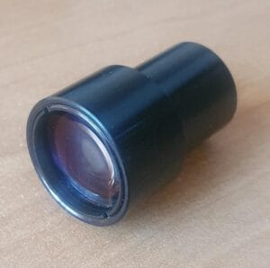
Optical design of the Retinoscope
From the point of view of optical design. A basic retinoscope can have a very simple configuration. It will have a light source, lens, and a movable barrel that can change the distance between the source and the lens. Additional elements include cards with the slit profile and focusing cards that helps the patient direct their sight into the device.

Retinoscopes are very useful when working with small children. Because it’s a less subjective test and less intimidating that using a traditional Phoropter.

Ophthalmoscope Optical Layout
Here, we will talk about the different instrumentation used by ophthalmologists and optometrists. As you can imagine, there are many restrictions when designing an optical instrument that will be used in a patient. It matters whether the instrument is meant to be used as a diagnostic tool or during surgery, and whether the patient is awake or unconscious.
Here, we will focus on optical instruments used in the diagnosis and evaluation of some human eye parameters. Some of you may have already encountered them during a regular eye exam.
For today’s entry, we will talk about one of the most basic optical instruments used by optometrists and family doctors: the funduscope. This instrument allows the doctor to see the back of the eye. They can observe the retina, the optic nerve, the macula fovea, and the vascular system (all these structures are sometimes referred to as the fundus of the eye). By looking at these structures, a doctor can diagnose different ailments like endocarditis, diabetes, glaucoma, separation of the retina, and hypertension.
There are three models of funduscopes: classical, panoptic, and indirect funduscope (that looks like a miner’s light). The first two are shown in Figure.

Optical Design
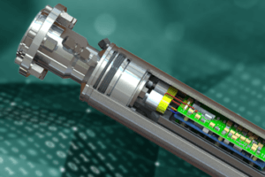
A funduscope consists of 3 essential elements: a light source, a mirror or beam splitter that redirects the light to the eye, and an optical means of correcting a non-sharp image of the fundus. In reality, they can be more complex. You normally want to control the amount of light and the size of the light source to adapt the light cone that goes into the patient’s eye.
In addition, you may need different colors of light source to enhance contrast or identify retinal lesions. Some instruments include grids as a basic measurement between retinal features. In order to correct the non-sharp fundus image, one can use a wheel of lenses with different powers or a movable lens that allows focusing at different points. An image of the instrument is shown in Figure 2.

Image from Delhi Journal of Ophthalmology
Finally, I would like to mention that when performing a test, an optometrist may require you to dilate your pupils. This is not always the case but it will depend on how much of the retina they need to observe.
Non-Contact Tonometers
This article concludes our exploration of optical instrumentation for optometry. If you’re new to this topic, I recommend checking out the sections on Ophthalmoscope Design, Keratometer Design, and Retinoscopy, which provide valuable insights into other key optometry tools. This week, we will talk about a very interesting optical device that uses the mechanical properties of the eye to make a measurement.
Internal ocular pressure is measured with non-contact tonometers, which aids in the diagnosis of glaucoma. The method of measurement is pretty intriguing. The patient is subjected to an air pulse that distorts the shape of his or her eye. The amount of distortion and the time it takes for the eye to return to its natural shape are then monitored using infrared light.
To fully comprehend this technology, we must first examine the biomechanics of the cornea. The cornea is depicted schematically in Figure 1.

Many biological tissues, including the cornea, have viscoelastic qualities. That is, depending on the rate at which a force is delivered, it will react differently. The so-called Newtonian Fluids, which a person can walk over if they move quickly or sink if they travel slowly, are another viscoelastic material that many readers may be familiar with.
The non-linear behavior of viscoelastic materials is an important factor to consider. When it comes to the cornea, The stress–strain curve can be broken down into sections to show changes in collagen organization during stress. The viscous reaction of ocular tissue is dominant at low distortion, whereas the elastic response is dominating at big deformation.
Due to copyright constraints, details on a commercial non-optical tonometer are difficult to come by. The fundamental layout of a non-contact tonometer is shown in Figure 2. As you may expect, we have two distinct systems. One is mechanical, which controls the puff of air, and the other is optical, which handles the measurements. We need to be able to manage the force and speed of air release for the air-puff, but we won’t discuss that mechanism here (this is an optic blog, after all).
A light source (typically infrared/visible), image optics, a photodetector (PD), and a position sensing detector are among the optical components (PSD). The cornea is in what is known as a “applanation state” after the air puff has been released. The cornea’s front portion flattens out like a mirror, reflecting the maximum amount of light from the lightsource into the PD.
This will be visible as a peak in reflection that gradually fades as the cornea returns to its original shape. The PSD was utilized to determine the corneal strain. To account for the image deformation caused by the light source and detectors being off-axis, we’ll require a cylindrical lens.

A photodetector (PD) and a
Position sensing detector (PSD) are syed to monitor the status of cornea applanation and the
cornea displacement, respectively. Image after Wai W Wang et al.
Non-contact tonometers are widely used, although they are not the only method for measuring intraocular pressure. Commercially available methods include the Ocular Response Analyzer (ORA) and Corneal Visualization Scheimpflug Technology (Corvis CT). Because of its imaging speed, noncontact nature, and high image quality, optical coherence elastography (OCE) has a lot of clinical potential.
Conclusion:
Function: A retinoscope is used to measure refraction and assess vision needs, while an ophthalmoscope is designed for examining the internal structures of the eye, including the retina, optic nerve, and blood vessels.
Application: The retinoscope aids in determining the appropriate vision correction, while the ophthalmoscope is essential for diagnosing eye conditions such as glaucoma, retinal detachment, and other retinal diseases.
Method of Operation: The retinoscope assesses the reflection of light from the retina to determine the necessary lens prescription, while the ophthalmoscope provides a direct visual inspection of the interior of the eye.
In summary, the retinoscope is primarily used to measure refractive errors, while the ophthalmoscope offers a detailed view of internal eye structures for diagnostic purposes. Combined with non-contact tonometers, these tools provide a comprehensive approach to eye examination and care.
FAQs: Eye Examination Optical Instruments
What is the primary purpose of a retinoscope?
A retinoscope is used to objectively measure a patient’s refractive error. By observing the motion of the red reflex across the pupil, the clinician determines whether the eye is myopic, hyperopic, or emmetropic, and estimates the corrective lens power required.
What causes “with motion” and “against motion” in retinoscopy?
The direction of red reflex motion depends on the location of the patient’s far point relative to the observer. If the far point lies behind the observer, the reflex moves with the slit. If it lies in front, the reflex moves against the slit. Neutralization occurs when the retina is conjugate to the retinoscope.
Why are retinoscopes well suited for examining children?
Retinoscopy is less subjective than patient-response-based tests and does not require verbal feedback. Because it relies on observing optical behavior rather than patient input, it is especially useful for examining small children or uncooperative patients.
What are the essential optical components of a retinoscope?
A basic retinoscope includes a light source, a lens, a movable barrel to adjust source-to-lens distance, and slit or card apertures. These components work together to project a controlled beam into the eye and allow observation of the reflected retinal illumination.
How does an ophthalmoscope differ functionally from a retinoscope?
An ophthalmoscope is designed for direct visualization of internal eye structures such as the retina, optic nerve, and blood vessels. In contrast, a retinoscope evaluates refractive error by analyzing reflected light motion rather than forming a detailed image of the fundus.
What optical elements are critical in ophthalmoscope design?
Key elements include a light source, a mirror or beam splitter to direct illumination into the eye, and a focusing mechanism to compensate for refractive differences between examiner and patient. Additional elements may control pupil illumination size and contrast.
Why are different illumination colors used in ophthalmoscopes?
Different wavelengths enhance contrast between retinal features and help identify specific conditions. Colored illumination can improve visibility of blood vessels, lesions, or nerve structures, aiding diagnosis without changing the optical geometry of the system.
What does a non-contact tonometer measure?
A non-contact tonometer measures intraocular pressure by applying a controlled air puff to deform the cornea. Optical sensors monitor corneal deformation and recovery, allowing pressure estimation without physical contact with the eye.
Why are non-contact tonometers considered safer for screening?
Because they do not touch the eye, non-contact tonometers reduce infection risk and patient discomfort. This makes them suitable for rapid screening and repeated measurements, especially in high-throughput clinical environments.
How do optical sensors detect corneal deformation in tonometers?
Infrared or visible light sources illuminate the cornea while photodetectors monitor reflected intensity. During applanation, the cornea temporarily behaves like a mirror, producing a reflection peak. Position-sensing detectors track corneal displacement throughout the deformation cycle.
Why are cylindrical lenses used in non-contact tonometer optics?
Cylindrical lenses correct image distortion caused by off-axis illumination and detection geometry. They help ensure accurate measurement of corneal deformation by compensating for asymmetric imaging conditions within the optical layout.
How do retinoscopes, ophthalmoscopes, and tonometers complement each other?
Together, these instruments provide a comprehensive eye examination. Retinoscopes assess refractive error, ophthalmoscopes visualize internal structures, and tonometers measure intraocular pressure. Each tool targets a different diagnostic parameter using distinct optical principles.
When are cardinal-point or paraxial approximations insufficient for these instruments?
Paraxial models are useful for early design, but wide pupils, off-axis viewing, and high numerical apertures introduce non-paraxial effects. Detailed ray tracing and tolerance analysis are required to ensure performance in real clinical conditions.