A designer of an IR optical system needs to account for key specifications that greatly impact the complexity of the device construction and its production cost. The most important requirements are described below.
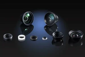
infrared optical systems
The maximum achievable theoretical resolution in wavelength infrared region
The maximum resolution is estimated with the help of Rayleigh criterion:
r=0.61λ/NA.
- r – minimum size of the object that can be recognized by an optical device
- λ – radiation wavelength
- NA – numerical aperture of the optical device
In accordance with this criterion, the resolving power of the optical device with thermal radiation (λ – about 10 µm) is 20 times lower than that of the visible radiation optical device (λ – about 0.55 µm).

According to the Rayleigh criterion, optics resolution can be increased by increasing numerical aperture (NA). In practice however, the real resolution is always lower than the theoretical limit because of optical aberrations. Therefore, a key design and manufacturing goal is to get as close as possible to the theoretical limit by correcting for optical aberrations.
High cost of optical materials for infrared optics
The cost of the optical materials used in infrared optical systems is rather high and can be the main cost driver for designed devices. To decrease the final price, optical engineers optimize the systems to enable minimizing expensive optical materials. The first step is to try to decrease the number of optical elements and making them as thin as possible. One approach for decreasing the number of optical elements is to use aspherical surfaces, a common practice which in infrared optics.
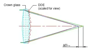
Diffractive optical elements (DOE) are sometimes used for this purpose. As a rule, DOE are a phase optical surface affected by a phase of transmitted light. DOE are usually included as circle zones on the surface of optical substrates like Fresnel lenses. The difference between DOE and a Fresnel lens is that the DOE hold strict phase difference 2π between adjacent zones.
One of the most useful advantages of DOE is in their dispersion features. Dispersion of DOE is opposite that of the refractive optical element. This makes it possible to correct chromatic aberrations without using additional elements. It also decreases the axial thickness of the optical elements, thus lowering cost. Moreover, DOE help to correct higher order optical aberrations.

Need assistance designing a custom optic or imaging lens ? Learn more about our design services here.
High absorption coefficient of the infrared optical materials
IR optical materials often have a high absorption coefficient (e.g. Germanium) which decreases the optical system efficiency. It may reduce the amount of incident light on the sensor decreasing the signal-to noise ratio. Moreover, a small amount of light on the sensor may lead to some data misrepresentation. This is one more reason why minimizing optical elements is recommended in infrared optics.
To know more about the selection of materials for IR optics, please check our previous post here.
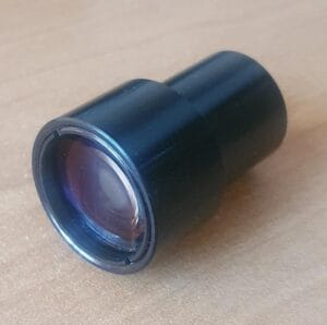
High refraction index of some infrared optical materials
Some optical materials used for IR optics production have a high refraction coefficient; Germanium’s refraction coefficient is about 4. This means the difference between the air and optical material refraction indices is rather high. This leads to a decrease in the amount of light propagating through the optical material/air interface, thus reducing the amount of useful light. Reflected light may result in glare and background noise.

Comparison of two focusing lenses produced from two different materials to be with different wavelengths.
Since the number of reflected rays is higher for germanium lens.
N-BK7 lens – 91.5% of the light is focused.
Germanium lens – 38.1% of the light is focused.
Simulation was conducted in OpticStudio software.
To minimize this, a high quality optical coating is required. Another approach is to lower the angle of the incident light on the two environments interface. This also decreases the amount of reflected light.
Spectral range of thermal radiation of metals
The spectral range of thermal radiation (longwave IR-radiation) is 8-15 µm. The maximum intensity of the metals’ thermal radiations under normal conditions is about 8-12 µm. If any part of the device made from metal is in the sensor’s field of view (not optics), the radiation emitted can reach the sensor sensitive layer. As a result, the level of stray radiation may be very high causing loss of image contrast and corruption of the obtained data. This can be aggravated by the fact that thermo-optical devices require highly sensitive sensors.
Care must be taken during optomechanical design to exclude the chance of placing metal parts in the sensor’s field of view.
Narcissus effect
Narcissus effect describes the existence of the “cold” (dark) background spot on the image. This spot exists due to the difference in luminosity between the sensor and other device parts. In fact, the dark spot is the image of the sensor.

Original image owned by Photonics Spectra. Dark (cold) central circle and ring around it are are result of the Narcissus effect.
The sensor sensitive surface of any thermo-optical device absorbs IR radiation and almost doesn’t emit it. If the device optical scheme has the wrong distribution, the background light noise is very non uniform. In the center of the image, dark spots can be seen. This happens when the image of the sensor is reflected by some surface and focused on the image plane. As a result, we can see the sensor image in the form of a dark spot (because of its low radiating capacity). A correctly designed optical system excludes the existence of the echo sensor image.
The temperature coefficient of refractive index
The value of the refractive index of some optical materials used in optical IR devices production strongly depends on temperature variations. This can lead to degradation of optical quality and distortion of obtained data. The temperature coefficient of the refractive index dictates how strong the variation of the temperature effect on the optical material refractive index. The lower this coefficient, the lower the temperature impact.
To increase the thermal stability of the IR optical device, consideration of the temperature coefficient is required.
Conclusion
Design of an IR-optical system requires specialized knowledge and skills in optical design. These issues need to be resolved during design to get a good quality optical system.
Want to learn more? This post provides a general overview of IR and thermal optics and find details on optical materials appropriate for thermal and IR imaging in this link.