Basic Concepts
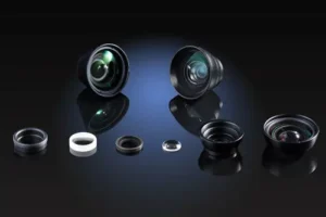
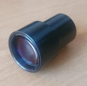
One of the most common optical structures is the achromatic doublet. It is used to reduce chromatic aberrations. At its most basic, it is a two lens system configuration where one lens is a concave lens, usually made of a flint glass, and the other is a convex element, usually made with crown glass.
Why these shapes and materials? We will try to explain the reason behind this structure.
Chromatic Aberration
First, we need to understand what is chromatic aberration and why it occurs. Chromatic aberration is the effect caused by the change in refractive index for a given material at different wavelengths. For example, BK7 has a refractive index of 1.5228 at 480 nm (blue) and of 1.5131 at 700 nm (red). That basically means that if we have a biconvex lens made with BK7, it will focus red and blue light at different points, resulting in chromatic aberration. This is shown in Figure 1.

FIGURE 1. 50MM Chromatic Aberration on a Biconvex Lens
In order to reduce chromatic aberration, we need to find a way to match the lens focal length regardless of the wavelengths we are using. A way to do this is by using an achromatic doublet. As mentioned before, the achromatic doublet has two lenses: a negative lens (concave) and a positive one (convex). The basic idea is that both lenses will compensate their respective dispersions and cancel each other.
Flint Glass vs Crown Glass
The negative component is usually made of what is called “Flint glass”. Flint glass has some lead and a particular high chromatic aberration (described by an Abbe number below 50), and high refractive index (usually above 1.55). Some types of flint glass are: F, LF, SF, KF, BaF, BaLF. Lead-free flint glass usually has a “N” before their name. For example N-SF8.
Crown glass on the other hand is used to fabricate the positive component. Crown glass has a low dispersion (with an Abbe number above 50) and low refractive index (usually below 1.5), although some glass like BK7 has a refractive index that overlaps with some flint glass. Crown glass names usually include a “K” at the end (form the german “kron”, crown). Some types of crown glass are: K, SK, BK, LaK, LaSK and many others.
Design of Doublets
A first approximation to design a doublet uses a two linear-equations system:

Equation 1
where f1, and f2 are the focal length of the first, and second element, respectively, and feq is the equivalent focal length of the system. The second equation we need is:

Equation 2
where V1 and V2 are the Abbe numbers for the first and second elements, respectively. Solving for f1, and f2 from Eq. 1 and Eq. 2, we get:


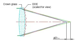
If we can correct the lens shown in Fig. 1 with an equivalent achromatic doublet, we will set feq to 50 mm and choose two materials for our lenses. For the flint glass, we choose N-SF8 with an Abbe number of 31.31 and for crown glass, we choose N-BK7 with an Abbe number of 64.17. Substituting these values into Eq. 3 and Eq. 4, we obtain values of 25.61mm and -50.48 for f1 and f2, respectively. Figure 2, shows a chromatic aberration using these numbers (note: the lens is not optimized).

Figure 2. 50MM AChromatic Doublet with minimum chromatic aberration
The combination of unique materials (flint glass and crown glass) and the lens shapes of the doublet, an optical engineer can use the science of light to deliver lens solutions without chromatic aberrations.
Achromatic Doublet Optimization
We will now review the steps necessary to optimize an achromatic doublet.
Before we start, we need to mention that there are different ways to optimize any design; there is no “formula” that an engineer can apply to yield the best results. It is a process that requires revisions and feedback. It is, in a sense, an art that benefits from the optical engineer’s technical knowledge. What is presented here is just a method we have used in the past with acceptable results.
Our variables
We start by assuming that we have the goals of our designs, that is, we have the focal length, wavelength range, aperture diameter, FOV already defined. Based on this information, we have several variables that we can manipulate, those are:
- Flint glass,
- Crown glass,
- Four radii of curvature (two for each lens),
- Separation between lenses
Based on these variables, we will try to optimize for three aberrations: chromatic, coma, and spherical aberrations
Correcting Chromatic Aberration
The first aberration that we will try to correct for is chromatic aberration. This is, after all, one of the main reasons we will be using an achromatic doublet. As mentioned in the early article, an achromat is formed by using a flint glass and a crown glass. Using the right combination of glasses will reduce chromatic aberration but the choice of glass can be daunting. How do we know what type of glass to use?
We first need to be familiar with the concept of the Abbe Number (or V-number), a measure of the dispersion of glass; the higher the Abbe number, the lower the dispersion. Figure 1 shown the Abbe diagram where we can plot the V-number versus the refractive index for several types of glass.

In theory, you can pick any combination of two glass types. although there are some guidelines that are helpful:
1. The glass of positive lens (crown glass) should have a higher Abbe number that the negative lens (flint glass)
2. A large difference in Abbe number will help us to have lower curved surfaces and will help in optimizing coma and spherical aberrations
3. The negative lens (flint glass) should preferably have a higher refractive index than the positive lens (crown glass)
Once the glass types have been chosen, we can calculate the focal length of each optical element in our doublet with the following equations

Equation 3
Equation 4
With the right combination of glass, we should be able to significantly bring down chromatic aberration.
Correcting Coma Aberration
In the previous step, we calculated the focal length of each lens, but we still need to define the radii of curvature. So let’s define those before attacking coma. To simplify (and reduce the length of this article), we will assume symmetric lenses with equal radii of curvature in the front and back surfaces of each lens. A first approximation for our lenses can be found using the following equations:

Equation 5

Equation 6
Now, to correct for coma, we will adjust the radii of curvature of the first and fourth surface, (i.e. the first surface of the first lens and the second surface of the second lens). In order to keep the optical power unchanged, we would like to have (1/R1)+(1/R4)=const. So, increasing one radius will decrease the other one. We will repeat this process until an acceptable coma reduction is achieved.
Correcting Spherical Aberration
The last aberration that we will correct for is spherical aberration. Once the first two aberrations are solved for, spherical aberration can be relatively simple to tackle. We may say that we have two tuning variables that we can modify to produce either a coarse or fine tuning. If we have a significant amount of spherical aberration, we can modify one of the internal radii of curvature of our lenses (i.e. surface two and three). If we have a small amount of spherical aberrations, we can modify the spacing between lenses.
When correcting for one aberration, we need to keep monitoring the whole system: more often than not, lens optimization is a matter of compromising. Sometimes it is not possible to completely reduce all aberrations simultaneously.
The presented method is just one that may help you to do a simple optimization. More complicated methods involve reducing chromatic aberration for a specific line and calculating coma coefficients for each optical element, and minimizing their combined effect. This method gives a better starting point to reduce aberrations.
There are also different configurations of achromatic doublets you may want to consider, for example: Littrow, .Fraunhofer and Clark doublets.
Example of Achromatic Doublet Optimization
Here we will show the process of achromatic doublet optimization. We’ll start with our requirements. We’re looking for a 50mm focal lens with a 20-degree FOV and 30 mm diameter.
We’ll start with a single BK7 biconvex lens, shown in Figure 2 along with its spot diagram.


From the spot diagram, we can see that there is significant coma (specially at full field) and some spherical aberration. Look at this entry to learn more about spot diagrams.
We calculate some of the Seidel aberrations and look at the Ray Analysis graphs (we should talk about them at another time). We calculate a chromatic focal shift of 1.5 mm along the axis, a maximum spherical aberration of 4mm at 20-degrees, and a Seidel coefficient for coma (third-degree) of 0.157.
Correction Chromatic Aberration
We will be using an achromatic doublet without referring to any specific application for this example. So we will be working with two common glasses: BK7 (abbe-number = 64.166 and n_green = 1.52237) and SF2 (Abbe-number = 33.819 and n_green = 1.6612). To calculate the radius of curvature for our lenses , we will be using equations 3 and 4.
From those equations we get an R_1 = 24.77 mm and R_2 = -59.33. At this point, we will have the same radii of curvature for the front and back surfaces, so we will have a biconvex and a biconcave lens, as shown in Fig 3


We still see significant coma and spherical aberration at this point: the chromatic focus shift however has decreased from 1.5 mm to less than 0.1 mm. There are no significant changes on spherical or coma at this point. So we will try to correct for coma next.
Coma Correction
At this point, we will be changing the radius of curvature of the first and fourth surfaces. We’ll try to keep the focal length as close as possible to 50mm. There are different ways you can try to do this optimization. OSLO and Zemax have different algorithms that can be used for different kinds of optimizations. For this example, however, we will just change the values in small amounts.

Figure 3 shows the changes on the first and fourth surfaces. We changed the first surface from 24.77mm to 23.8mm and the fourth surface from 59.33mm to 60.2mm. After these changes, the chromatic aberration is still under 0.1mm as before, but the Siedel Coma coefficient has been reduced to 0.0305 (from our original 0.157). Also the spherical aberration has been reduced to almost 2mm at 20-degrees, so we will try to improve it next.
Spherical Aberration
At this point we will try to achieve two objectives: reducing spherical aberrations and keeping the focal point as close to 50 mm as possible.
Let’s change the spacing between the first and second lens, and also the radius or curvature of the first surface of the second lens. We keep this iteration going until we reach the following lens combination.

We can see that our focal length is closer to our required 50 mm. We also still have our coma coefficient around 0.02 (just a little bit lower than before) and the spherical aberration less than 3 mm at 20-degrees.
We will stop our discussion about optimization here. As mentioned before, there are different ways to attack this problem, and there are more tools that we can use to analyze an optical system. In future blogs, we will talk about ray intercept graphs and we can return to another example of optimization or simple analysis.
FAQs: Achromatic Doublet Design and Optimization
What is an achromatic doublet?
An achromatic doublet is a two-element lens that reduces chromatic aberration by combining a positive element and a negative element made from glasses with different dispersion. The two elements are designed so their wavelength-dependent focal shifts partially cancel, producing a much smaller focus shift across the chosen band than a single-element lens.
Why do achromatic doublets usually use crown glass and flint glass?
Crown glasses typically have lower dispersion (higher Abbe number), while flint glasses typically have higher dispersion (lower Abbe number) and often higher refractive index. Pairing a low-dispersion positive element with a higher-dispersion negative element makes it possible to cancel a large portion of chromatic focus shift while maintaining a desired net focal length.
What is chromatic aberration and why does it happen?
Chromatic aberration occurs because refractive index changes with wavelength, so a lens bends different colors by different amounts. A single-material lens will generally focus blue and red light at different axial positions, producing blur, colored fringes, or focus shift across the spectrum. Achromatic designs reduce this effect by balancing dispersion between elements.
What is the Abbe number (V-number) and how does it guide glass selection?
The Abbe number is a measure of dispersion: higher Abbe number means lower dispersion. In a typical achromat, the positive element (often crown) has a higher Abbe number than the negative element (often flint). A larger Abbe-number difference can reduce the curvature needed to achieve achromatization, which can help with other aberrations.
Does higher refractive index always mean “better” glass for an achromat?
No. Higher refractive index can help reduce required curvature for a given optical power, but glass choice must balance index, dispersion, transmission, cost, manufacturability, environmental constraints, and availability. A “good” pairing is one that meets chromatic goals while keeping other aberrations and practical constraints under control.
What does “achromatic” mean in practice? Does it remove all chromatic effects?
Achromatic typically means the design substantially reduces axial chromatic focus shift over a defined wavelength range, often by bringing two wavelengths to the same focal plane. It does not eliminate all chromatic effects in every case. Residual secondary spectrum and lateral color can still exist depending on band, field, and system layout.
What design variables do optical engineers usually tune when optimizing an achromatic doublet?
Common tuning variables include the glass choice for each element, the four radii of curvature (two surfaces per lens), the spacing between elements (or cemented interface geometry), the stop location, and the operating conditions such as wavelength band, field of view, and f-number. Optimization typically balances chromatic, coma, and spherical aberrations.
How do you choose the focal lengths of the two elements for a target equivalent focal length?
A common starting point uses two equations: one that sets the combined optical power to match the desired equivalent focal length, and a second that enforces achromatization based on the Abbe numbers of the chosen glasses. Solving those gives initial element focal lengths that can later be refined by curvature and spacing optimization.
Why can reducing chromatic aberration make coma or spherical aberration worse?
Because the same surfaces and curvatures that control dispersion also influence third-order and higher-order aberrations. Achromatization can require curvatures or element powers that increase sensitivity to coma or spherical aberration. Optimization is often a compromise where improving one metric can degrade another unless additional degrees of freedom are introduced.
Which surfaces are commonly adjusted to reduce coma in a doublet?
A practical approach is to adjust the first surface of the first element and the last surface of the second element while trying to keep the overall optical power stable. By trading curvature between these outer surfaces, designers can reduce coma without dramatically shifting the target focal length, then re-balance other variables as needed.
How is spherical aberration typically reduced in an achromatic doublet?
Spherical aberration is often reduced by adjusting the internal radii (the interface-adjacent surfaces) for coarse tuning and then refining with small changes in element spacing for fine tuning. The specific best move depends on the aperture, f-number, and how the system is weighted toward on-axis performance versus field performance.
What are Littrow, Fraunhofer, and Clark doublets, and why do they matter?
These are named achromat configurations that use different bending and spacing choices to emphasize different performance goals, manufacturability, and sensitivity. Selecting a configuration influences how aberrations are distributed and how tolerant the design is to fabrication and alignment errors, so the “best” form depends on the application constraints.
When is an achromatic doublet a good choice, and when do you need something more complex?
Achromatic doublets are a good choice for many imaging tasks where reducing chromatic focus shift is important and a two-element solution is sufficient. If the system demands wide spectral bandwidth, fast f-number, wide field, tight distortion control, or very high MTF across the field, additional elements, aspheres, or advanced glass choices may be required.