Filters for selecting specific wavelengths are common in optical systems. In our microscope design article we explained the use of dichroic mirrors to select fluorescent wavelengths. In some applications optical engineers need to filter out high (UV light) or lower frequencies (IR light). These kinds of filters are called “Hot and Cold mirrors” .
For example in the design of a video projector we want the highest amount of lumens that your light engine can provide. Whether you are designing a movie projector or a DLP for a classroom, the brightness delivered by the projector will define the distance to the screen and ambient light condition the projector works best with.
A common light source in projectors are Metal Halide bulbs. Halides are brighter than LED sources (but not laser sources) and cheaper, but they have a couple of drawbacks: shorter life spans, they get really hot, and produce considerable amount of UV light. Specifically, heat and UV light are undesirable conditions because the heat can degrade some of the optical components while the UV light can hurt its users.
Understanding Hot and Cold Mirrors
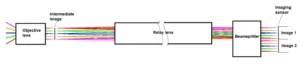
How do we then get rid of the heat and UV light? Well, you use a combination of hot and cold mirrors. Figure 1 shows a simple diagram of a projector system with a single DLP. In the figure, we can see that after the light source, we have a hot mirror: a dichroic filter that reflects UV light and transmits visible and IR light. After the color filter and relay lens, we have another filter. This filter (cold mirror), will transmit the IR wavelengths and reflect the visible light. Essentially, both mirrors have created a bandpass visible light filter.

Now, how do we design and fabricate a hot/cold mirror?
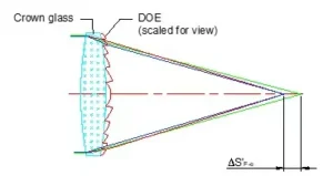
Dichroic filters are built using the principle of thin-film interference. Thin-films are structures with different refractive indices and a thickness usually smaller than the light wavelength. Light will bounce between the substrate, this-film, and air creating an interference pattern that will be either constructive or destructive. It is possible to design a thin-film that creates destructive interference below 400nm: light below 400nm won’t be transmitted but rather reflected. Figure 2 shows a basic configuration assuming only one reflection at each interface and a single thin-film structure.

We can create multiple thin-films on a single substrate giving sharper cut-off wavelengths or increasing the number of affected frequencies. One advantage of dichroic mirrors is that they have a longer life than traditional gel-based filters: their behavior is based on physical properties of the thin-film material giving little degradation due to heat or absorption.
We recently inserted a hot mirror into a VR headset application and have used mirrors in many past programs. Please drop us a line if you have questions about using such mirrors in your project.