Introduction
A 4F optical system is a system architecture that uses Fourier Optics. In this article, we will explain why we need them and how to design a simple 4f correlator. We will leave out most of the mathematical derivations, but if you are interested in digging more in depth, we highly recommend “Introduction to Fourier Optics, by J. Goodman”
Imagine a scene in an action movie in which intelligence intercepts a radio communication from a hostile cell. As you can imagine, the transmission is full of interference, noise, and it’s hard to understand the actual message. This is where the tech-savvy character presses a bunch of buttons and twists some knobs while saying something like: “we need to clean the signal and filter out the voices…” and voila, a second later, the message is clear of noise and we can understand whatever was said.
Well, the process of “cleaning” up a signal using filters is quite common in signal processing. Now here’s the catch: most of this filtering is done in the frequency domain. So we first need to convert our time-based signal into the frequency domain, filter out the unwanted components, and convert back to the time domain so we can hear it. That transformation between time-frequency is called Fourier Transformation, and as we apply it to electrical or voice signals, we can also apply it to images, but instead of time-frequency, the transformation is a space-frequency one.
Key Components of 4F Optical Systems
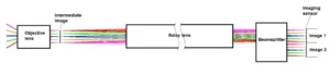
Before we continue this discussion, let’s take a look at a typical 4f correlator system

The 4f Correlator and Optical Relays
The 4f correlator stands as a fundamental element in the world of optics, serving as an optical relay that employs a configuration comprising two lenses. At its core, this innovative setup comprises an input plane positioned one focal length in front of the initial lens, while the output plane sits one focal length beyond the second lens. Nestled between these lenses lies the pivotal Fourier plane, a domain where the object placed at the output plane undergoes a transformative Fourier process.
The key to understanding the 4f correlator lies in comprehending its magnification, which is determined to be equal to -f2/f1. This mathematical relationship reveals that achieving a 1:1 relay, with a magnification of -1, is possible when both lenses share the same focal length. This crucial insight lays the foundation for precision and control in optical relays.
The Fourier Plane
Enter the Fourier plane, an intriguing space where optical manipulations unfold with finesse. Positioned between the lenses in the 4f correlator, this plane hosts the Fourier transformation of the object situated at the output plane. The magnification factor, as established earlier, plays a pivotal role in shaping the transformed image.
At this juncture, the placement of masks emerges as a powerful tool for sculpting the desired optical output. These masks, characterized by diverse shapes and opacities, act as filters that selectively modify the components of the original image. The Fourier transformation of an image bears resemblance to a diffraction pattern, where low-frequency components cluster near the optical axis, while higher-frequency ones extend farther from the origin.
Filters
In the Fourier plane of optical systems, a variety of filters can be strategically applied to achieve specific effects in image processing and optical manipulation. One common type is the low-pass filter, which allows low-frequency components near the optical axis to pass through while attenuating higher frequencies. This is useful for smoothing or blurring an image. Conversely, high-pass filters permit the transmission of high-frequency components, enhancing fine details and edges in an image.
Band-pass filters are designed to selectively transmit a range of frequencies, providing a valuable tool for isolating specific features within an image. Notably, notch filters can be employed to suppress or eliminate specific frequencies, addressing unwanted artifacts or interference. Phase-only filters, modifying only the phase of the Fourier spectrum, find applications in pattern recognition tasks.
These diverse filters, tailored to different frequency characteristics and spatial distributions, empower engineers and researchers to fine-tune optical outputs for varied applications, from image enhancement to noise reduction in optical systems. The strategic application of these filters in the Fourier plane allows for a nuanced control over the visual information within an image, offering flexibility and adaptability in optical processing.
Applications
The versatility of the Fourier plane becomes apparent as we explore the application of masks to filter out unwanted components from the original image. These masks, strategically placed at the Fourier plane, enable precision control over the optical output. The shape and design of these masks are tailored to specific applications, offering a customizable approach to optical manipulation.
In practical terms, if the objective is to eliminate high-frequency components from the image, a simple yet effective solution involves employing a mask with a spherical aperture on a back plate. This design allows only low-frequency components situated close to the optical axis to pass through, effectively removing the undesired high-frequency components. The ability to fine-tune optical output through mask manipulation in the Fourier plane opens up a realm of possibilities for researchers and engineers in various fields, from image processing to pattern recognition.
In essence, the 4f correlator and its associated Fourier plane serve as a dynamic duo in the toolkit of optical engineers, offering a sophisticated platform for precise optical transformations and tailored image processing. Understanding the intricacies of this setup provides a roadmap for harnessing its potential in diverse applications, unlocking new dimensions in optical innovation.
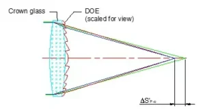
We most recently used a 4F system in a custom eye aberrometer. An eye aberrometer measures the wavefront of light as it goes through the eye. In an ideal eye, the wavefront would be completely flat. An aberrometer uses the changes on the wavefront to calculate Zermike polynomials and a topographic image of the distorted wavefront. This information can then be used to create custom corrected lenses, or corrective surgery (e.g LASIK). Our basic design is shown in Fig 2

Advantages and Limitations of 4f Optical Systems
4f optical systems present distinct advantages and limitations across various applications. One notable strength lies in their ability to achieve precise optical transformations. The configuration of two lenses and the Fourier plane allows for a 1:1 relay, enabling clear and detailed imaging. The Fourier plane’s versatility permits the strategic use of masks for tailored image processing, a valuable asset in fields such as pattern recognition and signal processing.
However, these systems are not without their limitations. One notable drawback is sensitivity to misalignments. Achieving and maintaining precise alignment between the lenses is crucial for optimal performance. Additionally, the inherent magnification characteristics can be a limitation in certain applications where a different magnification factor is desired. The optical complexity of 4f systems may also pose challenges in terms of system design and integration, potentially limiting their widespread adoption in certain practical scenarios.
In conclusion, the strengths of 4f optical systems lie in their precision and versatility, particularly in image processing applications. Nevertheless, careful consideration of alignment challenges and potential limitations is essential for their effective deployment in various scenarios.
Conclusion
Exploring the 4f correlator and its Fourier plane demystifies an optical relay system utilizing two lenses to shape light. The magnification dynamics, central to this setup, emphasize the importance of matching focal lengths for a 1:1 relay. Venturing into the Fourier plane reveals a space where masks of diverse shapes and opacities provide engineers a versatile toolkit for precise control over image components, reminiscent of a diffraction pattern. This dynamic interplay in optics offers nuanced solutions, from eliminating high-frequency elements to customizing optical outputs. Understanding these principles opens avenues for harnessing precision and innovation, propelling optical engineering into new realms of clarity and functionality.